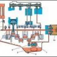
The ignition system - battery-operated, contactless - consists of an ignition coil, a switch, an ignition distributor sensor, spark plugs, spark plug tips, low and high voltage wires. The ignition system diagram is shown in the car electrical equipment diagram
Technical characteristics of the ignition system
- Firing order 1—2—4—3
- Distributor sensor type 19.3706
- Alternation of sparks, hail every 90±1
- Direction of rotation of the sensor-distributor roller (from the slider side) - Counterclockwise
- Ignition coil - B116
- Spark plugs - A14VR
- The gap between the spark plug electrodes is 0.8-0.95 mm
- Switch - 131.3734-01
- Candle tip - 50.3707200 or 402.37707230
- The resistance of the resistor in the tip is 4-7 kOhm
Ignition coil
An ignition coil is a transformer, on the iron core of which a secondary winding is wound, and on top of it is a primary winding.
The core with windings is installed in a sealed steel case, filled with oil and closed with a high-voltage plastic cover.
Ignition coil maintenance
To protect against possible breakdown of the plastic cover, the ignition coil must be cleaned of dirt, dust and oil, and the high and low voltage wires must be checked for secure fastening.
Checking the condition of the coil
Faults in the coil most often appear due to its overheating and operation with increased spark plug gaps.
Before removing the ignition coil for replacement, you should make sure that the wires are connected to the coil terminals in good condition and securely.
The coil should be checked on a special stand, model K-295.
A working coil should ensure uninterrupted sparking on a three-electrode needle gap with a spark gap of 7 mm at a frequency of 2500 min -1 of the sensor-distributor roller, no less.
If uninterrupted sparking is not ensured due to breakdown of the coil insulation, turn-to-turn short circuit, chips and cracks of the plastic cover, burnout of the cover, depressurization of the housing and oil leakage, the coil should be replaced.
Ignition distributor sensor
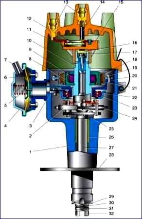
Ignition distributor sensor: 1 - housing; 2 - centrifugal regulator weight; 3 - bearing mounting screw; 4 - vacuum regulator; 5 - vacuum regulator spring; 6 - diaphragm; 7 - fitting; 8 - rotor magnetic circuit; 9 - permanent magnet of the rotor; 10 - rotor; 11 - cover; 12 - noise suppression resistor; 13 - conclusions; 14 - central contact; 15 - slider; 16 - felt; 17 - rotor fastening screw: 18 - stator winding; 19 - stator fastening screw; 20 - stator; 21 - magnetic circuit of the stator winding; 22 - stator support; 23 - bearing; 24 - weight spring; 25 - thrust washers; 26 - bushing; 27 - roller; 28 - octane corrector plate; 29 - washer; 30 - spring ring; 31 - pin; 32 - drive coupling
The distributor sensor is a combination of a magnetoelectric sensor and a high voltage pulse distributor.
The sensor-distributor shaft is driven into rotation by the oil pump drive gear.
The centrifugal ignition timing regulator automatically changes the ignition timing depending on the rotation speed of the distributor shaft.
The vacuum ignition timing regulator automatically changes the ignition timing depending on the engine load. The parameters of these regulators are shown in the table below.
Manual adjustment (when installing the ignition) is carried out by turning the distributor sensor in the drive housing. To turn, you need to loosen the bolt securing the distributor sensor.
Rotating the housing of the distribution sensor by one scale division corresponds to a change in the advance angle by 2° (according to the angle of rotation of the crankshaft).
Maintenance of the distribution sensor
Correctly and timely preventive measures prevent the occurrence of malfunctions and increase the service life of the distribution sensor.
At each TO-2, it is necessary to remove the high-voltage cover and the slider of the sensor-distributor and drop 4-5 drops of engine oil onto the filter (to lubricate the moving parts of the rotor).
It is necessary to ensure that the sensor-distributor is fastened.
If the distributor sensor is turned by hand, it should be secured after first checking that the initial ignition angle is set correctly; if necessary, set the starting angle.
The cover of the sensor-distributor must be thoroughly wiped outside and inside with a cloth soaked in clean gasoline.
Check carefully for cracks in the cover and slider or traces of breakdown by a spark and significant burning or corrosion of the electrodes of the cover and the current carrying plate of the runner.
Burning of the end surfaces of the current carrying plate of the runner and the cover electrodes indicates an excessively large radial gap between the current carrying plate and the electrodes.
The cover or slider in this case must be replaced.
If the cover or slider does not show signs of damage, you should carefully wipe the burnt areas of the electrodes of the cover and slider plate with a cloth lightly moistened with gasoline.
You cannot clean the indicated areas with a file. This leads to an increase in the gaps between the current-carrying plate of the runner and the electrodes of the cover and subsequently to a breakdown of the cover or runner.
High voltage wires must be inserted tightly into the terminals of the cover until they stop.
Burn and erosion on the inner surface of the cover sockets indicate that the wire is installed without fixation.
If the wire is loosely held in the socket, you must first slightly spread the petals of the spring tip of the wire and insert it into the socket until it stops.
The appearance of an additional spark gap in the high-voltage circuit due to the installation of high-voltage wires in the terminals of the cover without fixation usually leads to burnout of the plastic cover with subsequent failure.
If necessary, the distribution sensor can be checked on a special stand model K295 or K297.
If there is no stand, you should check the centrifugal regulator for jamming. The easiest way to do this is to check whether the slider easily returns to its original position if you turn it by hand relative to the stationary roller and then release it.
A distributor sensor with a faulty centrifugal regulator must be repaired or replaced.
The regulator is adjusted by changing the tension of the springs of the weights by bending the posts on which they are attached.
The small spring of the centrifugal regulator (weaker) must have a preload in the initial state, which is ensured by the position of the spring post.
Repair of the distribution sensor
Repair of the distributor sensor consists of replacing worn or faulty parts, followed by mandatory adjustment to ensure that the characteristics of the regulators correspond to the parameters specified above.
Disassembling the distribution sensor
Remove the distributor cap

Unscrew the three screws.

Pull the insulator out of the housing groove

Take out the stator.

Unscrew the two screws and remove the vacuum regulator.

Unscrew the two stator support screws.
Mark the relative position of the rotor and coupling on the roller.

Take out the felt

Holding the roller by the drive coupling from turning, unscrew the screw.

Remove the rotor from the roller

Remove the stator support complete with bearing.

Use a screwdriver to remove the spring ring.

Pull the pin out of the roller hole with the bead

Having removed the coupling with washers, take out the roller assembly with the centrifugal regulator
Before assembling the distributor sensor, lubricate the roller and its bearings with CIATIM-201 or No. 158 grease, and apply 1-2 drops of engine oil to the filter.
Assemble the sensor in the following order: install the roller and stator support in the sensor housing.

Place the vacuum regulator rod onto the support pin.

Install the stator and, making sure that the regulator rod has not come off the pin, tighten the two stator mounting screws.
We carry out further assembly in the reverse order of disassembly.
Check that the marks on the rotor and coupling match; if necessary, rotate the coupling on the roller 180°.
Checking the condition of parts
The lid and slider must be thoroughly wiped periodically. Wipe the terminal sockets of the high-voltage wires of the cover with special care.
The terminals inside the cover and the current carrying plate must be wiped without using any tools, as this may increase the gap in the high-voltage circuit, which is unacceptable.
The cover and slider with cracks and burns must be replaced.
Check whether the central contact of the cover moves freely. The runner must be tightly installed on the rotor.
Check for the presence of a flat spring in the slider seat.
Inspect the inner surface of the stator.
There should be no traces on the poles of the magnetic circuit from touching the rotor poles.
Check the resistance of the stator winding, which should be 400-450 Ohms, as well as the integrity of the wire connecting the stator terminal to the sensor terminal.
Inspect the outer surface of the rotor magnetic circuit. There should be no traces of contact with the stator in the poles of the magnetic circuit.
Check the radial play of the rotor on the roller, which should be no more than 0.2 mm.
If there is wear on the roller or rotor, replace them.
Check the bearings for seizing. If there is play in the bearing, it must be replaced.
If necessary, wash the bearing and fill 2/3 of its volume with CIATIM-221 lubricant. Check the serviceability of the conductor connecting the support to the body.
Check for wear on the coupling pin. If there is wear, the coupling must be replaced. Check the weights on the axles for binding.
If there is radial play of the roller above 0.2 mm, it is necessary to replace the bronze-graphite bushings.
The diameters of the roller must be within the range of 12,70,2 and 8.5 mm, and their runout relative to each other must not exceed 0.01 mm.
If wear exceeds the specified tolerances, the roller should be replaced.
Press out worn bushings and press in new ones. After pressing, expand them to a diameter of 12.7 mm.
Assembly
The sensor-distributor is assembled in the reverse order of disassembly.
Before assembly, it is necessary to lubricate all working surfaces of parts (roller, bearing, etc.) with CIATIM-221 lubricant.
During assembly, it is necessary to adjust the longitudinal play of the roller and rotor within 0.05-0.2 mm using adjusting washers.
The sensor must then be checked on the K295 stand or similar.
The vacuum regulator is not adjustable. The centrifugal regulator is adjusted by bending the spring struts.
With the engine not running, the ignition timing at the end of compression in the first cylinder should be 5° BTDC.
To install the ignition you need:
- - remove the cover of the sensor-distributor;
- - unscrew the spark plug of the first cylinder;
- - close the hole for the first cylinder spark plug with your finger;
- - turn the engine crankshaft until it starts to exit air from under your finger. This will happen at the beginning of the compression stroke;
- - making sure that compression has begun, carefully turning the engine shaft, set the ignition timing to 5°.
In this case, the second mark on the damper part of the crankshaft pulley should be located opposite the indicator rib of the timing gear cover.
- - loosen the bolt securing the octane corrector to the drive and by turning the housing of the sensor-distributor, set the octane corrector arrow to the middle position of the scale and tighten the bolt;
- - loosen the bolt securing the octane corrector to the sensor-distributor body;
- - press the slider with your finger against its rotation (to eliminate gaps in the drive) and slowly turn the housing until the red mark on the rotor aligns with the arrow on the stator of the sensor-distributor;
- - tighten the bolt securing the octane corrector plate to the sensor-distributor body and install the cover of the sensor-distributor in place;
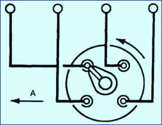
- - install high-voltage wires into the cover of the sensor-distributor in accordance with the order of operation of the cylinders 1-2-4-3 (Fig. 15)
After installing the ignition, check the accuracy of the ignition setting by listening to the engine while the car is moving.
To do this, warm up the engine to 60-90° C, moving in direct gear on a flat road at a speed of 30-40 km/h, give the car acceleration, sharply, all the way, pressing the throttle pedal.
If a slight and short-term detonation is heard, the ignition timing is set correctly.
In case of severe detonation, turn the housing of the distribution sensor one division of the octane-corrector scale counterclockwise (each division of the scale corresponds to a rotation of the crankshaft by an angle of 4°).
If there is complete absence of detonation, turn the housing of the sensor-distributor one notch clockwise, after adjusting the ignition timing, check its correctness by listening to the engine while the car is moving.
Adjust the ignition so that when the engine is under heavy load, only a slight detonation is heard.
With early ignition, when strong detonation is heard, the head gasket may be punctured and the valves and pistons may burn out.
When ignition is delayed, fuel consumption increases sharply and the engine overheats. Make more precise ignition settings using a strobe light.
To do this you need:
- - connect the strobe sensor-distributor to the high voltage wire of the spark plug of the first cylinder;
- - start and warm up the engine;
- - check the engine and, if necessary, adjust the crankshaft speed at idle within 550-650 rpm;
- - turn on the strobe and point it at the indicator rib on the camshaft gear cover, while the indicator rib and three fixed marks on the crankshaft damper pulley should be visible.
When the ignition is installed correctly, opposite the indicator edge there should be an area between the first and second marks of the damper pulley.
If the position of the indicator rib and marks does not correspond to the specified ones, it is necessary to loosen the bolt securing the distributor sensor to the drive housing and, with the engine running and the strobe light on, rotate the sensor distribution housing to the optimal position of the indicator rib and marks. Tighten the bolt.
It is strictly forbidden to leave high-voltage wires with tips that are not fully inserted into the sockets of the sensor-distributor cover as far as it will go, as this will lead to burnout of the cover.
Switch
The switch is designed to amplify the signals of the distribution sensor and control the ignition coil current in the primary circuit.
The performance of the switch can be checked on a stand model K295 or K297. If you don't have a stand, you can check the switch in a car.

")
")
")
")
")