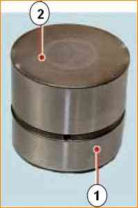
Hydraulic pushers of the VAZ-21126 engine, made in the form of cylindrical pushers located between the camshaft and valves, combine two functions:
transmitting force from the camshaft to the valves and eliminating gaps in their drive
The operation of the hydraulic pusher is based on the principle of incompressibility of engine oil, which constantly fills the internal cavity of the hydraulic pusher during engine operation and moves its plunger when a gap appears in the valve drive.
This ensures constant contact of the pusher with the camshaft cam without play.
This eliminates the need to adjust valves during maintenance.
Oil under the pressure necessary for the operation of the hydraulic pusher is supplied to the internal cavities “A” and “B” from channel B of the engine lubrication system through a side hole in the pusher 6, made in the annular groove of its cylindrical surface.
When valve 1 is closed, pusher 6 (through plunger 7) and sleeve 9 are pressed respectively against the camshaft cam 5 and the end of the valve stem by the expanding force of spring 8.
The pressure in cavities “A” and “B” is the same, check valve 3 of the hydraulic pusher is pressed to the seat in plunger 7 by spring 2 - there are no gaps in the valve mechanism.
When the camshaft rotates, the cam 5 runs into the pusher 6, moving it and the plunger 7 associated with it.
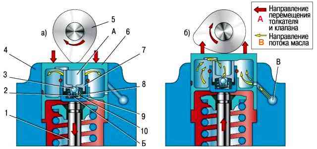
The movement of plunger 7 in sleeve 9 leads to a sharp increase in pressure in cavity “B”.
Despite small oil leaks through the gap between the plunger and sleeve, pusher 6 and sleeve 9 move as one piece and open valve 1.
With further rotation of the camshaft, cam 5 reduces the pressure on pusher 6 and the oil pressure in cavity “B” becomes lower than in cavity “A”
Check valve 3 opens and allows oil to pass from cavity “A”, connected to the engine oil line, into cavity “B”
The pressure in cavity “B” increases, sleeve 9 and plunger 7, moving relative to each other, select a gap in the valve mechanism.
The oil pressure supplied to the hydraulic tappets is regulated by a valve installed in the cylinder head.
Since after stopping the engine, oil flows from the channels coming from the oil pump into the oil sump, and the oil supply channels to the hydraulic tappets remain filled, after starting the engine, air plugs may form in the cavities of the latter.
To eliminate them, calibration compensation holes are provided in the engine oil supply channels, which ensure automatic purging of the cavities of the hydraulic pushers.
In addition, compensation holes make it possible to slightly reduce the oil pressure entering the hydraulic tappets at high engine speeds, when the pressure in the cavity of the hydraulic tappet can become so high that its pusher, resting on the back of the camshaft cam, will slightly open the valve at the moment , not corresponding to the valve timing.
Almost all faults of hydraulic pushers are diagnosed by the characteristic noise emitted by the gas distribution mechanism in various engine operating modes.
Noise from valves can sometimes be eliminated by slightly rotating the spring or valve around the longitudinal axis.
To do this, do the following.
Rotate the crankshaft to a position where the valve making the noise begins to open slightly.
Turn the spring a little and the valve will turn at the same time.
Start the engine. If the noise continues, repeat steps 1 and 2.
If turning the spring and the valve does not give the desired result, check the condition of the spring and measure the gaps between the valve stems and guide bushings.
Eliminate increased (compared to nominal) gaps.
If the valve and spring are in good condition, and the knocking of the valves is still heard when the engine is running, the hydraulic tappet is faulty. Replace it as follows.
Carry out the work 20–30 minutes after stopping the engine.
Remove the cylinder head cover.
Remove the distributor new shafts.

To check the hydraulic pusher, click on it.
If the hydraulic pusher is in working order, it should be recessed with significant force; if this force is small, the hydraulic pusher is faulty.
It is also necessary to check the ease of rotation of the hydraulic pusher in the socket of the block head.
If the hydraulic pusher does not rotate or rotates with great effort, it must be replaced.

Remove the hydraulic tappet from the cylinder head socket.
Remove the hydraulic pusher using a conveniently sized magnet.

Lubricate the hydraulic tappet and the socket in the cylinder head with engine oil and install the hydraulic tappet into the socket
The remaining hydraulic pushers are replaced in the same way.
Install the camshaft and timing gear drive parts in the reverse order of removal
After replacing the hydraulic tappet, the engine may run for a short time with increased noise during the first start until the hydraulic tappets are pumped.
To speed up pumping of hydraulic tappets, let the engine run at high speed for 1–2 minutes.
Possible malfunctions of hydraulic pushers, their causes and solutions
- Cause of malfunction
Remedy
Increased noise immediately after starting the engine:
Oil leakage from part of the hydraulic pushers during long-term parking.
Noise that disappears a few seconds after starting the engine is not a sign of a malfunction, since some of the hydraulic lifters, which were under the load of the valve springs of the open valves (the oil supply channels remained open), leaked oil, the deficiency of which is replenished at the beginning of engine operation
Intermittent noise at idle, disappearing as the engine speed increases:
- Damage or wear of the check valve ball
Replace the hydraulic pusher
- Contamination of the hydraulic pusher mechanism with wear products due to untimely oil changes or poor quality
Clean the mechanism parts from dirt. Use the oil recommended in the owner's manual
Increased noise during idling of a warm engine, disappearing at increased crankshaft speed and completely absent on a cold engine:
- Oil flow through the gaps between the plunger and the hydraulic pusher sleeve that have increased due to wear
Replace the worn hydraulic pusher assembly
Increased noise that occurs at high crankshaft speeds and disappears at low frequencies:
- Foaming when there is excess oil (above the top mark on the dipstick) in the oil sump due to its agitation by the crankshaft. If an air-foamy oil mixture gets into the hydraulic pushers, it disrupts their operation
Bring the oil level in the oil sump to normal
- Air intake by the oil pump when the oil level in the oil sump is too low
Bring the oil level in the oil sump to normal
- Damage to the oil receiver due to deformation of the oil sump when hitting a road obstacle
Repair or replace defective parts
Continuous noise of one or more valves, independent of crankshaft speed:
- The appearance of a gap between the pusher and the camshaft cam due to damage or contamination of the hydraulic pusher parts
Remove the cylinder head cover, install the camshaft cams one by one with the protrusions facing up and check for clearance between the pushers and the cams.
By pressing (for example, with a wooden wedge) the hydraulic pusher being tested, compare the speed of its movement with the others. If there is a gap or an increased speed of movement, disassemble the hydraulic pusher and clean its parts from dirt or replace the hydraulic pusher
*The following reasons are possible for increased noise in idle mode, which increases with increasing crankshaft speed up to 1500 min -1 and is not associated with the operation of hydraulic pushers:
- - increased clearances between valve stems and guide bushings;
- - terminal misalignment increased to a value exceeding the permissible value apana and saddles;
- - non-parallelism of the ends of the valve springs;
- - greater than permissible runout of the valve head chamfer.

")
")
")
")
")