Dismantling and assembling the cylinder head
Remove the cylinder head only to troubleshoot parts of the cylinder-piston group, cylinder head gasket, valves, or to replace the head itself
Remove the cylinder head in the following order:
- 1. Drain the coolant from the engine cooling system
- 2. Disconnect all pipelines from the head, protect their internal cavities from dust and dirt
- 3. Remove cylinder head cover
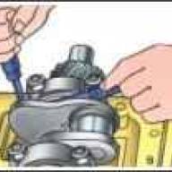
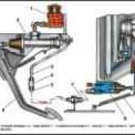
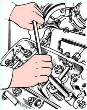
Unscrew the nuts of the nozzle mounting brackets (Fig. 1), remove the nozzles (Fig. 2), protecting the atomizer from impacts and clogging of holes
Unscrew the nuts securing the rocker axles, remove the rocker axles assembly with the rocker arms and remove the rods.
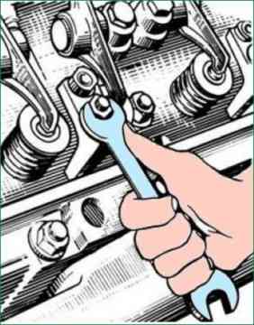
Unscrew the cylinder head nuts (Fig. 3), following the sequence reverse to tightening (Fig. 4) in at least three steps:
- - I - reception - up to 147-118 Nm (15-12 kgf m)
- - II - reception - up to 49-39 Nm (5-4 kgf m)
- - III- trick - unscrew the nuts.
- 7. Remove the cylinder head from the engine and inspect its condition.
- 8. If necessary, carefully remove the cylinder head gasket.
- 9. Check the condition of the cylinder liners and close the cylinder bores to protect them from dust and dirt.
Install the cylinder head on the engine in reverse order.
Before installing, wipe the mating surfaces of the cylinder block, the shoulder of the cylinder liner and the cylinder head with a clean rag.
Reuse of the metal cylinder head gasket is allowed with the same cylinder head only if the position of the liners in the cylinder block remains unchanged and there are no signs of gas breakthrough in the gas joint area.
Reuse of rubber gasket and seals is possible only if there are no cracks, damage, hardening.
Pay attention to the correct installation of the rubber gasket and seals.
The threads must be lubricated with clean engine oil.
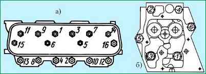
Tighten the cylinder head nuts on a cold engine in ascending order of numbers, as shown in fig. 4 in at least three steps:
- - I - reception - 39-49 Nm (4-5 kgf m);
- - II - reception - 118-147 Nm (12-15 kgf m);
- - III - reception - 216-235 Nm (22-24 kgf m).
After tightening with a second operation, check the required torque on each nut, following the sequence indicated.
Never tighten the nuts with a torque greater than indicated, as this will inevitably lead to the destruction of parts, and the tightness of the seal will not improve.
Lapping valves
Before disassembling the cylinder heads, clean them of oil and carbon deposits and mark the serial numbers of the valves on the ends of the plates in order to install them in their places during assembly.
To dry out the valves, it is necessary to install the cylinder head without injectors, rocker arms, rocker arm axles and rocker arm axle mounting studs with the mating surface on the plate so as to provide a stop for the valves.
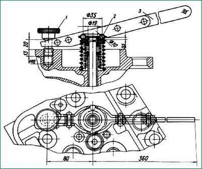
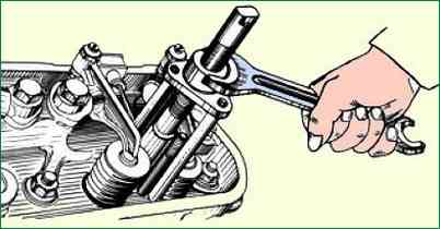
Drying out is carried out using the device shown in fig. 5.
For this purpose, screw the stop bolt 1 of the device into the hole for the stud for attaching the rocker arm axis, install the pressure plate 2 of the device on the spring plate of the corresponding valve and, pressing the handle 3 of the device lever, press the valve springs, remove the crackers and remove all parts of the valve assembly .
In the same way, successively dry all other valves and remove the valve springs and related parts.
Turn the cylinder head and remove the valves from the guides. Thoroughly clean the valves and seats from dirt, carbon deposits and oil deposits, rinse in kerosene or a special cleaning solution, dry and inspect to determine the degree of repair.
It is possible to restore the tightness of the valve by lapping only if there is slight wear and small holes on the working chamfer, and only if the plate and stem are not warped and there are no local burnouts on the chamfers of the valve and seat.
In the presence of such defects, lapping should be preceded by grinding seats and valves or replacing defective parts.
To lap the valves, use a special lapping paste prepared by thoroughly mixing three parts (by volume) of green silicon carbide micropowder with two parts of engine oil and one part of diesel fuel.
Stir the lapping mixture thoroughly before use, since in the absence of mechanical stirring, the micropowder can precipitate.
Mount the cylinder head on a plate or special tool with the mating surface up.
Apply a thin, even layer of lapping paste to the valve face, lubricate the valve stem with clean engine oil and install it in the cylinder head.
It is allowed to apply the paste on the chamfer of the saddle.
Lapping is performed by reciprocating rotational movements of the valves using a special tool or a drill with suction.
Pressing the valve with a force of 20-30 N (2-3 kgf), turn it ⅓ of a turn in one direction, then, loosening the force, 1/4 turn in the opposite direction.
Do not lap in a circular motion.
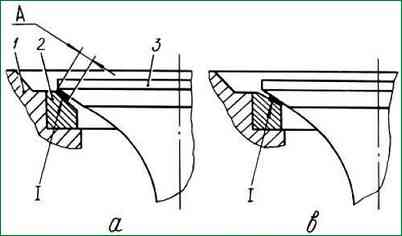
Periodically lifting the valve and adding paste to the chamfer, continue lapping, as indicated above, until a continuous matte belt with a width “A” of at least 1.5 mm appears on the chamfers of the valve and seat (Fig. 6).
Ruptures of the matte belt and the presence of transverse marks on it are not allowed.
When properly lapped, the matte "A" band on the valve seat bevel should start at the larger base of the cone, as shown in Figure 6.
After lapping, thoroughly wash the valves and cylinder head with kerosene or a special cleaning solution and dry.
Attention! The presence of even slight residues of lapping paste on the valve or cylinder head can lead to scoring and accelerated wear of the cylinder liners and piston rings.
Install the valves, springs and their mounting parts on the cylinder head and dry the valves using the tool (see Fig. 5).
Check the quality of grinding of the valve-seat interface for leaks by pouring kerosene or diesel fuel, pouring it alternately into the inlet and outlet channels.
Well-lapped valves should not let kerosene or diesel through for one minute.
Checking the quality of lapping with a pencil is acceptable.
To do this, apply 10-15 dashes at regular intervals with a soft graphite pencil across the chamfer of the lapped clean valve, then carefully insert the valve into the seat and, pressing strongly against the seat, turn it ¼ turn.
If the lapping quality is good, all the dashes on the working chamfer of the valve should be erased.
If the results of the lapping quality check are unsatisfactory, it must be continued.

")
")
")
")
")