Possible pump malfunctions may include: leakage of the diaphragm and valves, decreased elasticity or breakage of the diaphragm spring, wear of pump drive parts
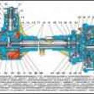
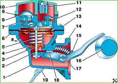
To disassemble the pump, remove the head cover 10 (see Fig. 1), gasket 9 and filter 8.
Then unscrew the screws securing the head 14 of the housing, separate the head from the diaphragm.
When removing the housing head, be careful not to damage the diaphragm, as the diaphragm will stick to the flanges of the head and pump housing.
Next, disassemble the drive mechanism, for which you first press out the axis 19 of the drive levers and remove the lever 17 and spring 16.
Carefully release diaphragm 6 and remove it and spring 5 and seal 3 with washer 4.
When disassembling the head, remove the inlet 7 and discharge valves. To do this, press out the valve races.
After disassembly, wash all parts in kerosene or unleaded gasoline, blow with compressed air, dry and check them.
The diaphragm must be sealed and its varnish coating must not have peeling.
If it is necessary to replace the diaphragm blades, assemble it using a special device (Fig. 3).
The diaphragm spring should have a height of 50+5 mm in the free state, and 15 mm under load (5 ± 0.2) kgf.
Check the elasticity of the pump spring using a model 357 GARO device. Valves must not have warpage, cracks, dents or visible signs of wear.
The valve springs must press the valves tightly against the seats without gaps. The pump drive levers and their axle should not have much wear.
The maximum gap between the lever axis and its bushing, as well as between the bushing and the levers, should be no more than 0.25 mm.
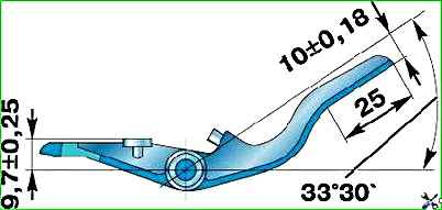
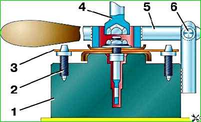
Particular attention should be paid to the wear of the working surfaces of the lever (Fig. 4) at the points of their contact.
Before assembly, check the fit of the head and pump housing flanges.
The deviation from the plane should be no more than 0.08 mm. If necessary, grind in.
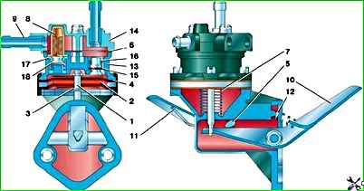
To disassemble the “Universal” pump (see Fig. 2), unscrew the screws securing the cover 14, remove the cover and filter element 8
Unscrew the screws securing the housing 13 to the bottom cover, separate them, remove the diaphragm assembly and spring 7.
Rinse all parts with gasoline and blow with compressed air.
Check the integrity of the springs.
Check for stuck valves.
Check the apertures. They should not be cracked or hardened.
After checking, replace all worn or damaged parts with new ones.
Always replace the pump gaskets with new ones and lubricate them with a thin layer of lubricant before installation.
Assemble the pump in the reverse order of disassembly.
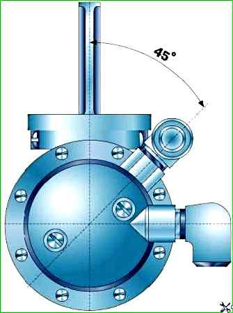
When installing the B9V-B pump head, its position relative to the housing must correspond to Fig. 5.
Tighten the head mounting screws with the diaphragm pulled to its lowest position using the manual pumping lever.
This assembly provides the necessary sagging of the diaphragm and relieves it from excessive tensile forces, leading to a sharp reduction in the durability of the diaphragm.
After assembly, check the pump on a model 527B or 577B GARO device.
At a camshaft rotation speed of 120 min –1 and at a suction height of 400 mm, the pump must ensure that the fuel supply begins no later than 22 s after switching on, creating a pressure of 150–210 mm Hg. Art. and a vacuum of at least 350 mm Hg. st.
The pressure and vacuum created by the pump must be maintained within the specified limits when the drive is turned off for 10 s.
Pump flow at a camshaft speed of 1800 min –1 must be at least 120 l/h.

")
")
")
")
")