UAZ vehicles are equipped with three types of mechanical three-shaft gearboxes:
- - four-speed, with synchronizers only in 3rd and 4th gears;
- - four-speed, with synchronizers in all forward gears;
- - five-speed, with synchronizers in all forward gears.
Four-speed gearboxes are interchangeable, but may have different sizes of input shaft splines (for different clutch drive discs).
Five- and four-speed gearboxes are interchangeable complete with their transfer cases and driveshafts.
When installing a five-speed gearbox instead of a four-speed one, it is also necessary to modify the body floor hole for the transfer case levers.
Assemblies and parts of different gearboxes are not interchangeable.
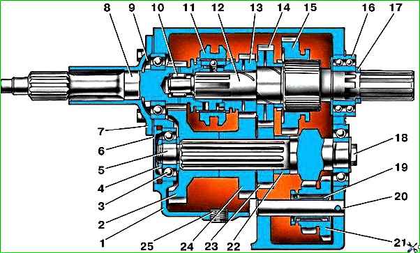
Gearbox, partially synchronized: 1 - crankcase; 2 - intermediate shaft drive gear; 3 - intermediate shaft bearing; 4 - nut; 5 - intermediate shaft; 6 - bearing cover; 7 - front cover; 8 - input shaft; 9 - special nut; 10 - front bearing of the secondary shaft; 11 - synchronizer clutch; 12 - secondary shaft; 13 - third gear gear; 14 - 2nd gear gear; 15 - 1st gear gear; 16 - rear bearing of the secondary shaft; 17 - retaining rings; 18 - bolt securing the rear bearing of the intermediate shaft; 19 - bearing of the reverse gear block; 20 - axis of the reverse gear block; 21 - reverse gear block; 22 - spacer sleeve; 23 - gear II of the intermediate shaft; 24 - third gear of the intermediate shaft; 25 - crankcase drain plug
fig. 1. Gearbox, partially synchronized
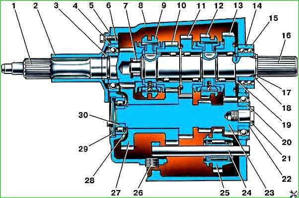
Synchronized gearbox: 1 - input shaft; 2 - front cover; 3 - special nut; 4,14,17,28 - retaining rings; 5 - gasket; 6,15,20,30 - bearings; 7 - front bearing of the secondary shaft; 8 - crankcase; 9 - synchronizer clutch for 3rd and 4th gears; 10 - third gear gear; 11 - 2nd gear gear; 12 - synchronizer clutch for 1st and 2nd gears; 13 - 1st gear gear; 16 - secondary shaft; 18 - washer; 19 - spacer ring; 21 - special bolt; 22 - disc spring; 23 - intermediate shaft; 24 - reverse gear axis; 25 - reverse gear; 26 - plug; 27 - block of gears for driving the intermediate shaft and 3rd gear; 29 - cover
fig. 2. Synchronized gearbox
The four-speed, not fully synchronized gearbox consists of a one-piece cast-iron crankcase in which the primary, secondary and intermediate shafts are mounted on ball bearings.
The front end of the secondary shaft rests on a roller full complement bearing in the bore of the rear end of the primary shaft, and the rear end rests on a double-row ball bearing, along which the gearbox and transfer case are centered.
The drive gears of the intermediate shaft, as well as 2nd and 3rd gears, are helical, constant mesh.
Splines are installed on the intermediate shaft of the gears of the 2nd and 3rd gears.
Bronze bushings with holes and honeycomb knurling are pressed into the holes of the gears of the 2nd and 3rd gears of the secondary shaft to improve lubrication.
Radial holes in the gears and helical grooves on the shaft are used to supply oil to the bushings.
III and IV gears are engaged by moving the inertial synchronizer clutches on the secondary shaft.
The driven spur gear of the 1st gear moves along the splines of the secondary shaft.
I gear is engaged by moving the driven gear backward along the splines of the secondary shaft until its teeth engage with the teeth of the drive gear.
Moving the 1st gear driven gear forward engages 2nd gear (its splined rim is connected through the 1st gear gear to the secondary shaft).
In addition, the driven gear has a middle position. In this case, it is used to engage reverse.
The reverse gear block is placed on a cage needle bearing, sliding along an axis pressed into the crankcase.
When the gear block moves forward along the axis, its large gear engages with the 1st gear drive gear, and the small gear engages with the driven gear on the secondary shaft.
At the same time, the primary and secondary shafts begin to rotate in different directions and the car moves backward.
The gear shift mechanism consists of a cover in which three rods with forks are installed, a shift lever with a spring, and that Also a spring-loaded fuse that prevents accidental reverse gear.
Fixation of engaged gears is carried out by spring-loaded balls that fit into holes on the rods.
A locking device in the form of two plungers and a pin on the rod of the 3rd and 4th gears does not allow engaging two gears at the same time.
The gearbox is lubricated with transmission oil poured into the crankcase.
For filling and draining oil, fill and drain holes are used, closed with plugs with conical threads.
The four-speed, fully synchronized gearbox differs from the one described in that:
- - all forward gears are engaged by moving the clutches of two inertial synchronizers installed on the secondary shaft;
- - gears of 1st, 2nd and 3rd gears are helical, constant mesh, mounted on the secondary shaft on double-row roller bearings with plastic cages;
- - the front end of the intermediate shaft rests on a radial roller bearing;
- - the driven gear of the intermediate shaft drive and the third gear drive are made in the form of a block pressed onto the smooth part of the intermediate shaft;
- - the driving helical gears of 1st and 2nd gears and the spur gear of the reverse gear are made integral with the intermediate shaft;
- - reverse gear is activated by moving the reverse intermediate gear until it engages with the spur gear of the intermediate shaft and the ring gear of the synchronizer clutch for 1st and 2nd gears.
In addition, this box has different gear ratios in all gears except 4th gear.
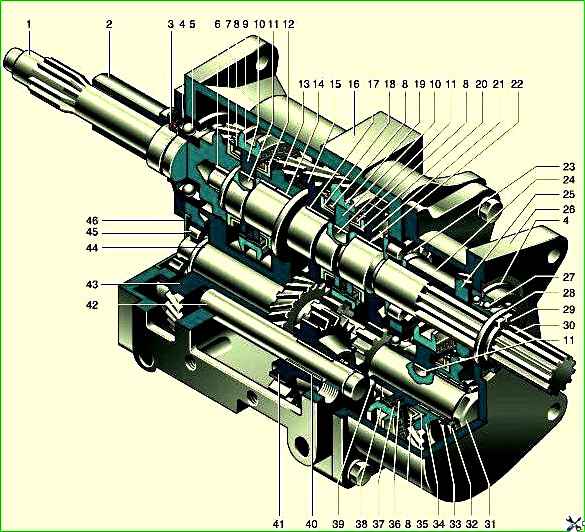
Five-speed gearbox: 1 - input shaft; 2 - bearing cover; 3 - input shaft cuff; 4 - retaining ring; 5 - ball bearing of the input shaft; 6 - roller bearing of the secondary shaft; 7 - spline rim of the input shaft; 8 - blocking ring; 9 - synchronizer clutch for III-IV gears; 10 - coupling hub; 11 - key; 12 - spline ring of the 3rd gear gear; 13 - third gear gear; 14 - gear bushing; 15 - 2nd gear gear; 16 - crankcase; 17 - 2nd gear bushing; 18 - splined ring of the 2nd gear gear; 19 - synchronizer clutch for 2nd-1st gears; 20 - splined ring of the 1st gear gear; 21 - 1st gear gear; 22 - bushing of the 1st gear gear; 23 - roller bearing of the secondary shaft; 24 - secondary shaft bushing; 25 - 5th gear driven gear; 26 - 5th gear housing; 27 - double-row ball bearing of the secondary shaft; 28 - spline washer; 29 - retaining ring; 30 - secondary shaft; 31 - bolt; 32 - disc spring; 33 - support ring; 34 - drive gear of 5th gear; 35 - splined ring of the 5th gear drive gear; 36 - synchronizer spring; 37 - synchronizer block; 38 - 5th gear synchronizer clutch; 39 - ball bearing of the intermediate shaft; 40 - roller bearing of the reverse gear; 41 - reverse gear; 42 - reverse gear axis; 43 - gear block for driving the intermediate shaft and 3rd gear; 44 - intermediate shaft; 45 - roller bearing of the intermediate shaft; 46 - bearing cap
The five-speed gearbox is designed on the basis of a fully synchronized four-speed gearbox and is distinguished by the fact that the 5th gear housing is bolted to the rear wall of its crankcase.
The crankcases are centered using two mounting sleeves.
The secondary and intermediate shafts are made longer.
A double-row angular contact ball bearing for the secondary shaft is located in the rear wall of the 5th gear housing, and an additional radial roller bearing is installed in the bore of the rear wall of the gearbox.
At the rear end of the intermediate shaft, a driving (large) helical gear of fifth gear with an inertial synchronizer is installed on a double-row needle bearing.
The driven (small) gear of the 5th gear is located on the splines of the secondary shaft.
When V gear is engaged, the secondary shaft rotates faster than the primary, therefore V gear is called accelerating.
Thanks to its use, the number of crankshaft revolutions is reduced at high vehicle speeds, which increases engine life and saves fuel.
The 5th gear parts are lubricated from the common oil bath of the gearbox.
To reduce oil leakage, a rubber cuff is installed in the cover of the input shaft of the five-speed gearbox.
Maintenance
During operation, check the oil level and replace it within the time limits specified in the lubrication table.
If a leak is detected, find out the cause and replace the faulty parts (gaskets, plugs, etc.).
Periodically check the fastening of the gearbox, as well as the fastening and adjustment of the gearbox control mechanism sideways on vehicles of the UAZ-3741 family.
The tightening torque of the bolts and nuts securing the gearbox to the clutch housing and transfer case should be from 39 to 55 Nm (4.0–5.6 kgf m). The gearboxes themselves have no adjustments.

")
")
")
")
")