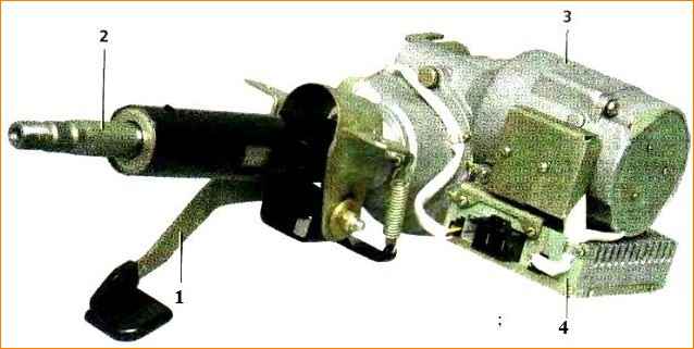
The steering is safety-resistant, with electric power steering and a height-adjustable steering column
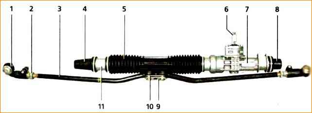
The steering mechanism is rack and pinion type with a variable gear ratio.
It is secured in the engine compartment on the front panel of the body with two brackets through rubber supports. The fastening bolts are welded, two on each side of the front panel.
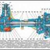
The steering gear housing is cast, made of aluminum alloy. On the right side, a pipe with a longitudinal groove is inserted into the crankcase, secured in the crankcase with a nut.
The crankcase contains a helical drive gear (pinion shaft), which meshes with the rack.
The rack has oblique teeth cut with variable pitch (closer to the ends of the cut part of the rack, the pitch of the teeth decreases).
To reduce the load on the gear shaft and its bearings under extreme operating conditions, a plastic gear bushing with a metal support plate is inserted into the crankcase.
The gear shaft rotates on two bearings: the front (at the end of the shaft) is a needle bearing, the rear (closer to the steering column shaft) is a ball bearing.
Since axial loads can be high in helical gearing, a thrust roller bearing is additionally installed on the drive gear shaft, consisting of a plastic cage with rollers of the lower (inner) and upper (outer) rings.
The lower bearing ring is pressed onto the drive gear shaft until it touches the inner ring of the ball bearing, and the upper ring is installed in the crankcase cover.
In addition, the crankcase cover presses the outer race of the ball bearing against the end of the bearing seat.
The drive gear oil seal is installed in the cover, and there is an O-ring between the cover and the steering gear housing.
The cover is closed with a protective cover (boot) mounted on the drive gear shaft.
The rack is pressed against the gear teeth by a spring through a stop sealed in the crankcase with a rubber ring.
To reduce friction, a plastic insert is installed between the stop and the rack.
The spring, in turn, is tightened by the adjusting nut (internal octagon “24”).
At the factory, when assembling the steering mechanism, a gap of 0.1 mm is set in the engagement of the rack with the gear, after which the crankcase threads are cored (pressed) at two points (without damaging the nut).
The other end of the rail rests on a plastic sleeve, which is inserted into the pipe behind the longitudinal groove.
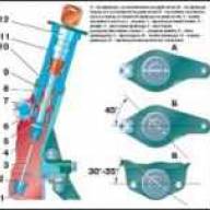
Adjustment of the gap between the gear and rack is carried out after disassembling the steering mechanism or if knocking occurs during operation.
The gap can only be adjusted with the steering mechanism removed. Set the rail to the middle position and block it from moving.
Having removed the rubber plug, insert the leg of the dial indicator into the hole of the stop adjusting nut until it touches the rack stop.
By rotating the pinion shaft (torque 15 Nm), while the gear pushes the rack and the stop, we determine the amount of movement of the stop using the indicator.
If it exceeds 0.05 mm, by tightening the adjusting nut, we achieve the specified amount of movement of the stop.
After this, having unlocked the rack, we check the ease of rotation of the pinion shaft throughout the entire range of travel of the rack.
The crankcase pipe is covered with a protective corrugated cover.
The rods are attached to the rack with bolts passing through the connecting plates and spacer bushings of the rubber-metal hinges, as well as the rod support mounted on the rack.
The spontaneous loosening of the bolts is prevented by a locking plate placed on the bolt heads.
To lubricate the gear, rack and bearings, use FIOL-1 lubricant (approximately 20-30 g for the entire mechanism).
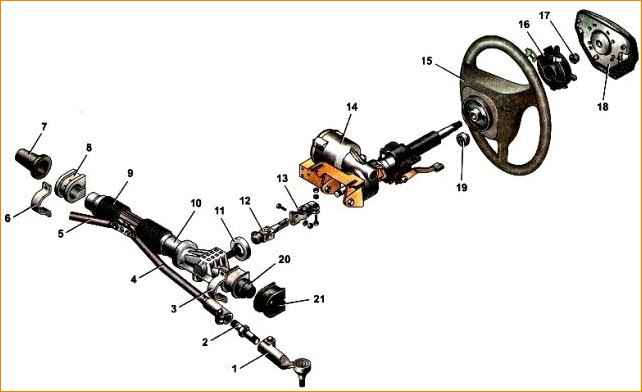
The steering shaft is connected to the gear shaft through an intermediate cardan shaft.
The steering shaft rotates in two ball bearings, one of which is installed in the steering column bracket pipe, and the second in the electric power steering housing.
The steering column bracket is secured with nuts at four points:
- front part - to the pedal bracket, rear part to the bracket on the body.
The steering column bracket and its pipe are hingedly connected to each other by two plates through plastic and metal bushings, tightened with four bolts.
Thus, the pipe can move in a vertical plane relative to the bracket, allowing you to adjust the position of the steering wheel in height.
Movement is limited by the length of the slots in the plates.
To fix the pipe relative to the bracket, use the steering column position adjustment lever.
It is connected to the adjusting sleeve with a splined hub and secured to it with a retaining ring.
The bushing is screwed onto a coupling bolt passing through the slots in the guides of the plastic pipe and bracket.
A spacer sleeve is installed on the bolt. The bolt head is secured against turning by a special protrusion.
When the lever is turned down, the bushing turns away and the tightening force of the plates weakens, which allows you to manually change the position of the steering column.
Springs are installed between the plates and the bracket, pulling the bracket pipe to the upper position when the connection is loosened.
After installing the steering column in the required position, the lever is raised up and the connection is tightened, fixing the column.
The steering drive includes two integral tie rods and swing arms welded to the shock absorber struts of the front suspension.
Each rod, in turn, consists of three parts - an inner tip, an outer tip and an adjusting threaded sleeve.
The adjusting sleeve is a tube with a hexagon at the end, with external and internal threads of different directions.
The length of the tie rod changes when the adjusting sleeve is rotated.
After the adjustment is completed, the outer tie rod ends are bolted together.
The steering rod is connected to the swing arm through an outer end with a ball joint.
To protect against dirt, the hinge is covered with a rubber protective cover (boot).
The hinge forms a non-separable structure with the tip, so if it fails, the tip should be replaced with subsequent adjustment of the wheel toe.

Electric power steering allows you to reduce the effort on the steering wheel, making it easier to drive.
The basis of the electric booster is a brushless electric motor with a gearbox located under the steering casing.
A worm is installed on the motor shaft, which meshes with a plastic gear mounted on the steering shaft.
The electronic control unit coordinates the operation of the electric booster by changing the voltage supplied to the electric motor using information received from sensors of vehicle speed, crankshaft speed and the amount of torque on the steering shaft.
The electric motor turns the steering column shaft through a gearbox with a certain torque.
The control unit provides sufficient steering information in all vehicle driving modes.
When the car is stationary, the torque on the shaft created by the electric amplifier is maximum; as the vehicle speed increases, the “assistance” of the amplifier decreases and the steering wheel becomes “heavier.”
If the electric booster fails, the car retains full controllability, while the steering wheel becomes somewhat “heavier” than on a car without an electric booster, since an additional load appears in the form of a freely rotating electric motor rotor.
B In the instrument cluster there is a fault indicator for the electric power steering. It lights up when the ignition is turned on and goes out after the engine starts.
If the electric booster is faulty, the indicator light is constantly on. The electric booster does not work when the engine is not running.
The electric amplifier can be turned off:
- - when the on-board network voltage decreases;
- - in the absence of a signal from the speed sensor and the engine speed is above 1500 rpm.
Such shutdowns are built into the operating algorithm of the electric amplifier and are not signs of a malfunction.
Steering play (free play of the steering wheel in the straight ahead position, measured along the rim of the steering wheel), no more than 5˚ or 18 mm.
Tightening torques for steering control threaded connections
Name of components – Thread - Tightening torque, Nm (kgcm)
- Steering mechanism mounting nut M8 - 15-18.6 (1.5-1.9)
- Steering column mounting nut M8 - 15-18.6(1.5-1.9)
- Nuts of coupling bolts securing the intermediate shaft flanges M8 - 23-27.4 (2.3-2.8)
- Tie rod coupling bolt M10x1 - 19-30.9 (2.0-3.2)
- Steering wheel mounting nut M16x1.5 - 31.4-51 (3.2-5.2)
- Nut for fastening the ball pin M12x1.25 - 27.1-33.4 (2.8-3.4)
- Bolt securing the steering rod to the steering mechanism M 10x1 - 70-86 (7.1-8.6)
- Steering gear bearing nut M38x1.5 - 45-55 (4.6-5.6)
Checking the technical condition of the steering
1. Visually check the condition of the protective covers of the tie rod ends and steering mechanism.
Damaged covers (torn, cracked) must be replaced.
2. Make sure that the steering column locking lever is raised all the way.
Trying to move the steering wheel in a vertical plane, we check that the steering column is securely fastened with the locking mechanism.

If the steering column moves, remove the steering column pads, use a 10 mm wrench to loosen the lever fastening bolt (left thread) and use a 17 mm wrench to tighten the nut of the steering column fixing lever axle.
After this, tighten the bolt.

- 3. Trying to move the steering wheel along the axis of the steering shaft, we make sure that there is no play in the steering wheel on the splines of the shaft and shaft in the steering column
- 4. To check the play in the steering, turn the steering wheel to the position corresponding to straight forward movement.
We place a slotted screwdriver on the instrument panel so that its blade is located next to the rim of the steering wheel (for reliability, it can be secured with masking tape).
Turning the steering wheel to the right until the wheels begin to turn (selecting play), and then to the left and guided by the blade of a screwdriver, with chalk, pieces of wire or in another way, mark these positions on the rim.
The play should not be more than 5° (or 18 mm) when measured along the outside of the rim.
Increased play indicates the need to troubleshoot and fix the problem. As a rule, the first thing to fail in the steering system is the tie rod ends.
5. To check that there is no play in the tie rod ends, an assistant slightly rocks the steering wheel from side to side.
Place your hand at the junction of the steering rod with the swing arm of the suspension strut so that your palm touches them at the same time.
When play appears in the tie rod end, a displacement of the swing arm relative to the rod will be felt.

- 6. Check the tightness of the nuts on the steering column universal joint bolts.
- 7. We repeat the check on the other side of the car. We replace faulty hinges.
- 8. When rocking the steering wheel from side to side, listen to the operation of the steering mechanism.
A knocking sound from the right edge of the steering mechanism indicates wear of the support sleeve.
We remove the faulty steering mechanism and repair or replace it.
9. Turn on the ignition - the electric power steering fault indicator light on the instrument panel should light up.
Start the engine.
Control room The light should go out and the steering wheel should turn easily with one hand.
If the lamp lights up while the engine is running, it indicates a malfunction of the electric amplifier and the need for repair.

")
")
")
")
")