The power steering operates as follows.
When moving in a straight line, screw 15 (Fig. 1) and spool 20 are in the middle position.
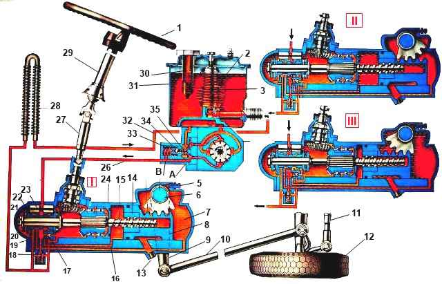
Scheme of operation of the power steering: 1 - steering wheel; 2 - hydraulic system filter safety valve spring; 3 - filter; 4 - power steering pump; 5 - bypass valve; 6 - bipod shaft with gear sector; 7 - rear cavity of the hydraulic booster; 8 - piston-rack; 9 - bipod; 10 - longitudinal thrust; 11 - transverse thrust; 12 - front wheel of the car; 13 - magnetic plug; 14 - ball nut; 15 - screw; 16 – steering gear housing; 17 - check valve; 18 - safety valve of the steering mechanism; 19 – power steering control valve; 20 - spool; 21 - thrust bearing; 22 - reactive plunger; 23 – centering spring; 24 - angular gearbox; 25 - front cavity of the hydraulic booster; 26 - discharge line; 27 – cardan shaft; 28 - radiator; 29 - steering column; 30 - filling filter; 31 - pump reservoir (hydraulic booster); 32 - drain line; 33 - bypass valve spring; 34 - safety valve of the pump; 35 - bypass valve; A and B - throttling holes; I - movement straight or neutral; II - turn right; III - turn left
Injection lines 26 and drain 32, as well as both cavities 7 and 25 of the hydraulic cylinder are connected.
Oil passes freely from pump 4 through control valve 19 and returns to hydraulic system reservoir 31.
When the driver turns the steering wheel 1, screw 15 rotates.
Due to the resistance to rotation of the wheels, which initially holds the wheels 12 and the piston-rack 8 in place, a force arises that tends to move the screw in the axial direction in the corresponding direction.
When this force exceeds the pre-compression force of the centering springs 23, the screw moves and displaces the spool rigidly connected to it.
In this case, one cavity of the power steering cylinder communicates with the discharge line and is disconnected from the drain line, the other, on the contrary, remains connected to the drain and is disconnected from the discharge line.
The working fluid supplied from the pump to the corresponding cavity of the cylinder exerts pressure on the piston-rack 8 and, creating additional force on the sector of the shaft 6 of the steering bipod, contributes to the rotation of the steered wheels.
The pressure in the working cavity of the cylinder is set proportional to the amount of resistance to wheel rotation.
At the same time, the pressure in the cavities under the jet plungers 22 increases.
The greater the resistance to turning the wheels, and therefore the higher the pressure in the working cavity of the cylinder, the greater the force with which the spool tends to return to the middle position, as well as the force on the steering wheel. Thus, the driver gets a “feeling of the road.”
When the steering wheel stops turning, if it is held by the driver in the turned position, the spool, under the action of centering springs and increasing pressure in the reaction cavities, moves to the middle position. In this case, the spool does not reach the middle position.
The size of the gap for the passage of oil into the return line will be set so that in the pressurized cavity of the cylinder, the pressure necessary to hold the steered wheels in the rotated position is maintained.
If the front wheel begins to turn sharply while the car is moving straight, for example due to hitting some obstacle on the road, the bipod shaft, turning, will move the piston-rack.
Since the screw cannot rotate (the driver holds the steering wheel in one position), it will also move axially along with the spool.
In this case, the cylinder cavity, into which the piston-rack moves, will be connected to the pump discharge line and separated from the return line.
The pressure in this cylinder cavity will begin to increase, and the blow will be balanced (softened) by the increasing pressure.
The screw, nut, balls, thrust bearings, as well as the angular gear, propeller shaft and steering column are loaded with relatively small forces when the hydraulic booster is operating.
At the same time, the gearing of the steering mechanism, the bipod shaft and the crankcase perceive the main force created by the oil pressure on the piston-rack.
Warning. When the hydraulic booster is not working, the steering mechanism still ensures that the wheels turn, but the ball screw and other parts are already subject to full loads.
Therefore, during prolonged operation with the hydraulic system not working, premature wear appears and breakdowns of the mentioned parts may occur.
Driving with the power steering inoperative, including towing a vehicle, must o be kept to a minimum.
The steering drive includes longitudinal and transverse steering rods (Fig. 2).
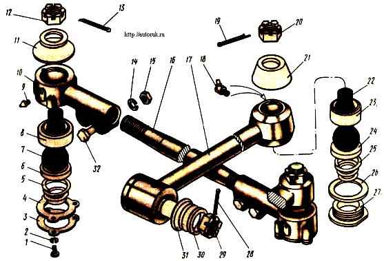
The longitudinal link connects the bipod of the steering mechanism with the upper arm of the left steering knuckle and is made with non-adjustable hinges.
The hinges include a ball pin 22, upper 23 and lower 24 liners, a spring and a threaded cover 27 with a lock washer 26.
The steering linkage transverse rod is tubular, with threaded ends onto which ends with ball joints are screwed.
By turning the rods in the tips, the toe-in of the steered wheels is adjusted. Each tip is fixed with two 32 bolts.
The transverse link joints are also non-adjustable and consist of a ball pin 7, an upper 8 and a lower 6 liner, a spring 5 and a cover 3 secured through a sealing paronite gasket 4 on the end of the link.
Rubber protective pads are used to protect them from dust and dirt.
The hinges are lubricated through grease nipples.
In the steering drive of cars with a 6X 6 wheel formula, the transverse steering rod is bent so that its middle part moves freely under the main drive housing of the front drive axle.
Therefore, the toe-in of the front wheels on these cars is adjusted by moving the tips on the rod, unscrewing the bolts 32 and rotating the tips on the threads, taking into account that the thread pitch on the left and right tips is different.
Steering maintenance
During daily maintenance, check the condition of the steering drive (without using special tools).
At service 1:
- - check the oil level in the reservoir of the power steering pump, if necessary, add oil to the specified level;
- - lubricate the steering rod joints through the grease nipples until fresh grease appears in the gaps.
Check the oil level in the pump reservoir with an indicator mounted in the filler plug of the reservoir, with the front wheels set straight. Before removing the plug, thoroughly wipe it and the filler neck of the tank with a rag moistened with diesel fuel or kerosene.
The oil level should be between the marks on the indicator. If necessary, add oil to the specified level with the engine running at minimum crankshaft speed. Fill the oil through a funnel with a double mesh and a filler filter installed in the neck of the tank.
At service 2:
- - check the clearances in the joints of the steering rods and driveshaft;
- - check and, if necessary, restore the free play of the steering wheel within acceptable limits;
- - remove and wash the pump filter.
For modernized cars. During maintenance (service 2), it is possible to replace the pump filter if it is significantly clogged.
Check the free play of the steering wheel with the vehicle equipped (without load) with the engine running at an engine speed of 600-1200 min -1.
The tire pressure should be normal, set the front wheels straight. The free play of the steering wheel on a new car should not exceed 15°.
The maximum permissible free play is 25°. Measure the free play with the K-402 or K-187 device, turning the steering wheel to the right and left until the left front wheel begins to turn.
Count the angle on the angular scale of the device from the conventional zero, which is set in the middle of the range of free swing of the steering wheel.
If the free play of the steering wheel is greater than permissible, check the presence of air in the power steering hydraulic system, the condition of the steering rod joints, the fastening and adjustment of the steering mechanism, the clearances in the steering driveshaft joints, the tightening of the driveshaft mounting wedges, and the adjustment of the steering wheel hub bearings. . If the tightening or adjustments are incorrect, restore them. If it is impossible to eliminate the gaps in the hinges or splines of the steering propeller shaft, replace the shaft.
Wash the filler filter and filter element with gasoline. If the filter elements are significantly clogged with resinous deposits, additionally rinse them with solvent 646 GOST 18188-72.
To change the oil and bleed the power steering system:
- Disconnect the trailing link from the steering arm or raise the front axle so that the steered wheels do not touch the ground. Remove the power steering pump reservoir cap.
Do not fill or bleed the steering hydraulic system with the tie rod connected or the wheels not raised.
- Turn the steering wheel all the way to the left and open the drain hole by removing the magnetic plug from the steering gear housing. Drain the oil until it completely flows out of the hole.
- Rinse the pump, pipelines and hydraulic booster, to do this:
- — unscrew the filter from the pump reservoir manifold and remove the remaining contaminated oil from the power steering pump reservoir;
- — wash the parts of the disassembled filter and the drain plug of the steering mechanism, clearing them of dirt. After cleaning and rinsing, assemble the pump filter and screw it into place;
- — pour 2 liters of clean oil into the pump reservoir through a funnel with a double mesh and drain through the drain hole of the steering gear housing, turning the steering wheel from lock to lock.
- Fill with fresh oil and remove air from the system in the following order:
- — screw the magnetic plug into the drain hole of the steering gear housing;
- — remove the rubber cap from the bypass valve of the steering mechanism and put a transparent elastic hose on its spherical head, the open end of which is lowered into a glass vessel with a capacity of at least 0.5 liters. The vessel must be filled with oil to half its volume;
- — unscrew the steering gear bypass valve 1/2-3/4 turn;
- — install the pump reservoir cap;
- — turn the steering wheel to the left until the centering springs begin to compress (determined by increasing force on the steering wheel; do not turn the wheel all the way);
- — remove the filler plug from the pump reservoir cap and from a container with a capacity of at least 1.5 liters, pour oil into the pump reservoir until its level stops decreasing;
- — start the engine and, while operating at minimum speed, add oil to the pump reservoir, not allowing its level to drop, until the release of air bubbles from the hose placed on the bypass valve stops;
- - close the bypass valve;
- — turn the steering wheel to the right until the centering springs begin to compress (determined by increasing force on the steering wheel) and return it to the left position again. Keeping the steering wheel in the left position, unscrew the bypass valve 1/2-3/4 turn and again watch for the release of air bubbles. After the bubbles stop, close the bypass valve;
- — repeat the previous operation at least two times, as a result, clean (without air) oil should come out of the bypass valve. If the release of air bubbles from the hose continues, repeat the operation one or two more times; At the same time, monitor the oil level in the pump reservoir, maintaining it between the marks on the level indicator;
- — stop the engine;
- — remove the hose from the spherical head of the bypass valve and put the protective cap on it;
- — check the oil level in the pump reservoir and, if necessary, add it. Install the filler cap of the tank;
- — connect the longitudinal steering rod to the bipod of the steering mechanism.
When refueling the hydraulic system, keep in mind that poor-quality oil pumping, which leaves air in the hydraulic system, is a common cause of the “heavy steering wheel” defect (increased force on the steering wheel), as well as decreased steering sensitivity and poor road holding. ” by car.

")
")
")
")
")