During daily maintenance, we drain the condensate from the system receivers after the trip.
Condensate should be drained from the receivers at the nominal air pressure in the system, moving the drain cock rod to the side
Pull the rod down. If the condensate has a high oil content, this indicates a compressor malfunction.
If the condensate freezes in the receivers, you need to warm it up with hot water or warm air.
Checking the condition of the trailer hoses.
When maintenance is 1:
- - inspect all elements of the brake system;
- - adjust the stroke of the brake chamber rods.
The stroke of the brake chamber rods is adjusted when the brake drums are cold and the parking brake is off.
The stroke of the rods must be adjusted if it is more than 40 mm.
We measure the stroke of the rod with a ruler, placing it parallel to the rod, resting its end against the brake chamber body.
Mark the location of the extreme point on the ruler scale.
After this, press the brake pedal all the way, the air pressure should be at least (6.2 kgf/cm 2), the parking brake system is turned off, and again mark the location of the same point of the rod on the scale .
The difference between the obtained values will be the stroke value of the rod.

We adjust the stroke of the rod by turning axis 1 (Figure 1) of the worm of the adjusting lever, having first unscrewed the lock 4 two turns. By rotating the axis, we set the minimum stroke of the rod.
Make sure that the wheel rotates freely, without any jamming, and tighten the lock.
After this, we check the gap between the pads and the brake drum through windows 2 in the shield.
After adjusting the stroke of the brake chamber rods, there may be the following gaps between the pads and the brake drum: at the expanding fist 0.4 mm, at the axles of the pads 0.2 mm.
It is also necessary to take into account that the difference in the stroke of the rods of the left and right wheels should have the same stroke as possible (no more than 2 or 3 mm), so that the wheels of the right and left sides brake equally;
- - lubricate the expansion cam shaft bushings through a grease nipple using a syringe, making no more than 5 strokes with the syringe;
- - lubricate the adjusting levers of the brake mechanisms until fresh grease is squeezed out.
- - in the autumn and winter, we replace the alcohol in the freezer protection. To do this, first drain the sediment from the housing by unscrewing the drain plug.
To add alcohol and control its level, lower the rod handle to the lower position and fix it by turning it 90˚ (when the rod is in the lower position, the safety switch is off).
Then we unscrew the plug with the level indicator, fill in 0.2 or 1 liter depending on the capacity of the fuse and close the filler hole.
To turn on the fuse, lift the handle up. To increase the effectiveness of the fuse, when filling the pneumatic system with air, you need to press the thrust handle 6 times.
When maintenance is 2:
- - we check the performance of the pneumatic drive of the brake system using the valves of the control terminals;
- - check by external inspection the cotter pins of the brake chamber rods;
- - tighten the nuts securing the brake chambers to the brackets and the nuts of the bolts securing the brake chamber brackets to the caliper;
- - adjust the position of the brake pedal relative to the cabin floor, ensuring full travel of the brake valve lever.
Checking the performance of the pneumatic brake drive consists of determining the output parameters of the air pressure along the circuits using control pressure gauges and standard instruments in the cabin (two-pointer pressure gauge and a block of brake system warning lamps).
Check the control valves installed in all circuits of the pneumatic drive, and the “Palm” type connecting heads of the supply (emergency) and control (brake) lines of the two-wire drive and the “A” type connecting line of the single-wire brake drive of the trailer.
Control terminal valves are located:
- - drive circuits for the front axle service brakes - on the pressure limiting valve;
- - drive circuits for the working brake mechanisms of the rear bogie - on the right (along the direction of the vehicle) frame spar in the rear axle area;
- - drive circuits for the parking and emergency brake systems - on the left frame side member in the rear axle area and in the circuit receiver;
- - the drive circuit of the auxiliary brake system and consumers - in the circuit receiver.
Before checking, we eliminate the leak of compressed air from the pneumatic system. As control technological pressure gauges, use pressure gauges with a measurement limit of 0 - 980.7 kPa (0 - 10 kgf/cm 2) accuracy class 1.5.
We check the functionality of the pneumatic brake drive in the following order:
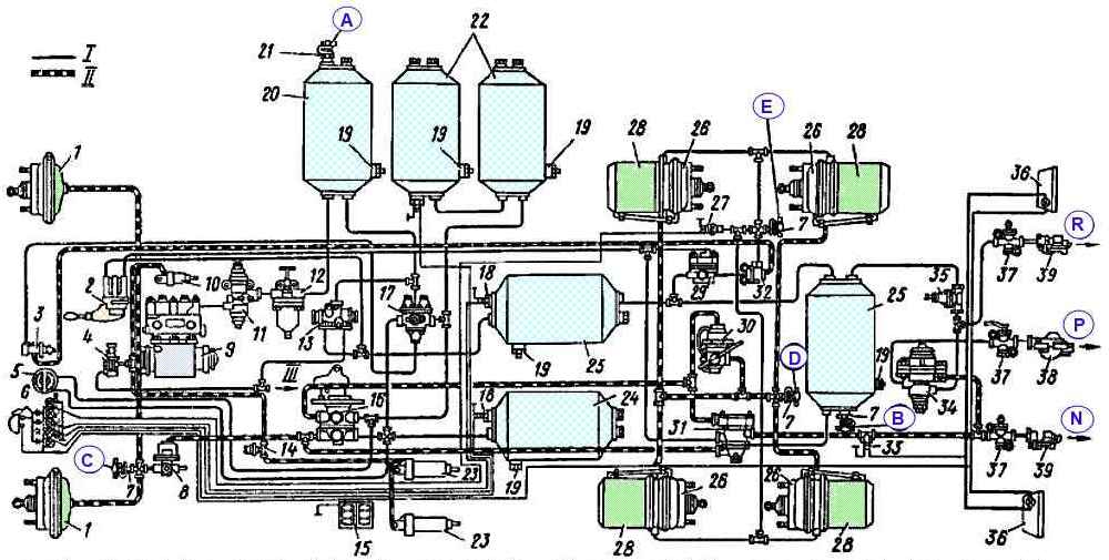
- - fill the pneumatic system with air until pressure regulator 11 is activated (see Fig. 2).
In this case, the pressure in all circuits of the brake drive and connecting head 39 of the “Palm” type of the supply line of the two-wire drive of the trailer brake mechanisms (terminal “R”) should be 608 - 735.5 kPa (6.2 - 7.5 kgf/ cm 2), and in the connection head 38 type “A” of a single-wire drive (terminal “P”) - 470.8 - 519.8 kPa (4.8 - 5.3 kgf/cm 2).
The control lamps on the instrument panel should go out when the pressure in the circuits reaches 441.3 - 539.4 kPa (4.5 - 5.5 kgf/cm 2). At the same time, the noise alarm (buzzer) stops working;
- - press the service brake system drive pedal fully. The pressure on the two-pointer pressure gauge should drop sharply by no more than 49.5 kPa (0.5 kgf/cm 2).
In this case, the pressure in the control valve “B” should be equal to the reading of the upper scale of the two-pointer pressure gauge in the cabin.
The pressure in the control valve “C” must be at least 225.6 - 264.9 kPa (2.3 - 2.7 kgf/cm 2) (for an unloaded vehicle).
Lift up the vertical rod of the regulator drive 30 braking forces by the amount of static deflection of the suspension.
The pressure in the brake chambers 26 must be determined using the lower scale of a two-pointer pressure gauge; the pressure in the connecting head 39 of the “Palm” type of the brake line of a two-wire drive (terminal “R”) should be 608 - 735.5 kPa (6.2 - 7.5 kgf/cm 2), in the connecting head 38 type “A” of the connecting line (terminal “P”) the pressure should drop to 0;
- - install the crane drive handle 2 to the front fixed position.
The pressure in the control outlet valve “E” must be equal to the pressure in receiver 25 of the parking and spare circuits and be within the range of 608 - 735.5 kPa (6.2 - 7.5 kgf/cm 2), the pressure in the connecting head 39 type “Palm” of the brake line of a two-wire drive (terminal “R”) should be equal to 0, in the connecting head 38 type “A” (terminal “P”) 470.8 - 519.8 kPa ( 4.8 - 5.3 kgf/cm 2);
- - install the crane drive handle 2 of the parking brake system in a vertical fixed position.
The parking brake system warning light on the warning lamp unit should light up and flash.
The pressure in the valve control terminal "E" and in the connection head 38 type "A" (terminal "P") should drop to 0, and in the connection body head 39 of the “Palm” type of the brake line of a two-wire drive (terminal “R”) should be 608.0 - 735.5 kPa (6.2 - 7.5 kgf/cm 2);
with the valve handle 2 in a vertical fixed position, press the emergency brake release button 3.
The pressure in the control valve "E" must be equal to the reading of the two-pointer pressure gauge 5 in the cabin.
The brake chamber rods of the intermediate and rear axle mechanisms must return to their original position;
- - release the emergency brake release button. The pressure in the control valve "E" should drop to 0;
- - press tap 4 of the auxiliary brake system mechanism. The rods of pneumatic cylinders 23 for controlling the dampers and pneumatic cylinder 10 for turning off the fuel supply should extend.
The air pressure in the brake chambers of the trailer (semi-trailer) must be equal to 58.8÷68.6 kPa (0.6÷0.7 kgf/cm 2).
In the process of checking the functionality of the pneumatic brake drive, when the pressure in the circuits drops to 441.3÷539.4 kPa (4.5÷5.5 kgf/cm 2), the buzzer should turn on and the lights should light up indicator lamps of the corresponding circuits on the instrument panel.
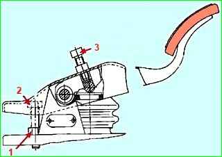
Adjust the position of the brake pedal relative to the cabin floor.
Adjust according to the pedal installation diagram (Fig. 3) on the brake valve.
By adjusting the installation and adjusting bolts, it is necessary to ensure that the pedal platform is positioned at an angle of 35˚±2˚ and the free play of the pedal is 10-15 mm.
Secure the installation bolt with a lock nut, cover the adjusting bolt with sealant before adjustment.
With maintenance - 3:
- - we check the condition of the brake drums, pads, linings, tension springs and expansion cams with the hubs removed: we eliminate malfunctions;
- - secure the receiver brackets to the frame.
When maintaining the brake mechanism, pay attention to the distance from the surface of the linings to the heads of the rivets. If this distance is less than 0.5 mm, change the brake pads.
Protect the linings from contact with oil, since the frictional properties of oiled linings cannot be completely restored by cleaning and washing.
If you need to replace one of the left or right brake linings, change all the linings on both brake mechanisms (left and right wheels).
After installing new friction linings, treat the block.
For a new drum, the radius of the block should be 199.6÷200 mm.
After boring the drum during repair, the radius of the block should be equal to the radius of the bored drum.
Drums can be bored to a diameter of no more than 406 mm.
The expansion cam shaft should rotate freely in the bracket without jamming.
Otherwise, clean the supporting surfaces of the shaft and bracket, check the condition of the shaft sealing rings, and then lubricate them through a grease nipple.
The worm axis of the adjusting lever should turn freely, without jamming.
Otherwise, wash the inner cavity of the lever with gasoline, dry it and fill the adjusting lever with fresh lubricant.

")
")
")
")
")