The low pressure fuel pump is installed on the high pressure fuel pump (on the rear cover of the speed controller) and is designed to supply fuel from the tank through the coarse and fine filters to the high pressure pump
The low pressure fuel pump is driven by the camshaft eccentric of the injection pump through the pusher and its rod 13; consists of a housing 1, a piston 12 with an eye 10, held by a plug 11, a rod 13, a pusher with a bushing, a suction valve 8 and a discharge valve 3 with springs (Fig. 1).

A piston-type manual fuel pump is secured to the low-pressure pump body with a hollow bolt. Therefore, the cavity under its piston communicates with the above-piston cavity of the low-pressure fuel pump.
The fuel pump consists of an aluminum cylinder and a plastic piston with a rubber sealing ring and is designed to fill filters, fuel lines with fuel and remove air from the fuel system before starting the engine.
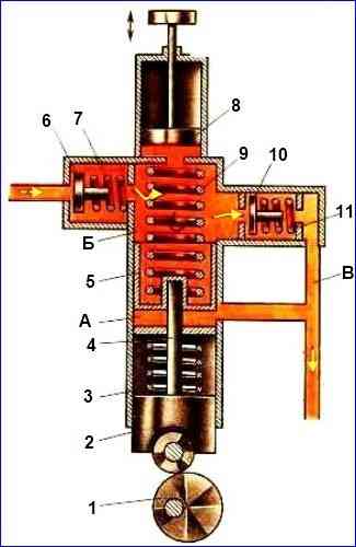
When piston 8 (Fig. 2) is moved upward using the handle, a vacuum is created underneath it, suction valve 6 opens and fuel enters cavity “B” of the low-pressure fuel pump.
During the reverse movement, piston 8 presses on the fuel, the suction valve closes, and the discharge valve 10 opens and fuel is supplied to the fine filter.
After pumping the system, piston 8 is lowered down and its handle is fixed in the lower position by turning, while the piston is pressed tightly against the gasket.
To maintain the helical groove on the rod, working in contact with the steel pin, the plastic handle should be turned with pressure on it.
Piston 5 of the low-pressure fuel pump makes two strokes: preparatory and working.
The preparatory stroke occurs when the piston moves upward: under the action of the rotating eccentric 1 by the pusher 2 and the rod 4, the piston 5 is pushed upward, compressing the spring 9.
In this position of the piston 5, pressure is created in the suction cavity “B”, and a vacuum is created in the discharge cavity “A” and fuel through channel “B” is displaced by the piston 5 into the cavity “A”.
In this case, part of the fuel, equal to the volume occupied by the rod in cavity “A”, flows to the fine filter.
The working stroke occurs when moving down: the protruding part of the eccentric moves away from the pusher, and the piston, under the action of a compressed spring 9, moves down and displaces fuel from cavity “A” into the fine filter.
At the same time, a vacuum is created in cavity “B”, and it is filled with a new portion of fuel through the opened suction valve 6.
The low pressure fuel pump supplies more fuel than is necessary for engine operation.
Therefore, if the pump piston stroke remains constant all the time, the pressure in the fuel line increases quickly.
As fuel consumption decreases, the pressure in cavity “A” increases and the compressed spring cannot overcome the fuel back pressure.
As a result, the piston stroke decreases and the piston hangs, loses contact with the pusher, and accordingly the fuel supply to the pump decreases.
As the engine fuel consumption increases, the pressure in cavity “A” decreases, the piston stroke increases and the fuel supply by the pump increases.

")
")
")
")
")