The electrical equipment system of KamAZ vehicles is single-wire with a rated voltage of 24 V. The negative poles of current sources and current consumers are connected to the vehicle ground
The negative terminal of the batteries is connected to the vehicle ground through a switch, so all electrical consumers operate only when the batteries are connected to ground.
To ensure reliable contact between the cab and the frame, the frame and the engine, additional ground wires are used.
In the general scheme of electrical equipment, groups of devices can be distinguished that form independent systems, the most important of which are the power supply system, including:
- - batteries and generator set with voltage regulator;
- - engine starting system, consisting of a starter, batteries and starting aids;
- - a system of instrumentation, which includes a speedometer, tachometer, instruments for measuring temperature, pressure, fuel level and current, as well as external and internal lighting systems, light alarms, heating, sound alarms and windshield wipers.
Some devices cannot be clearly classified into systems and can be classified as additional equipment.
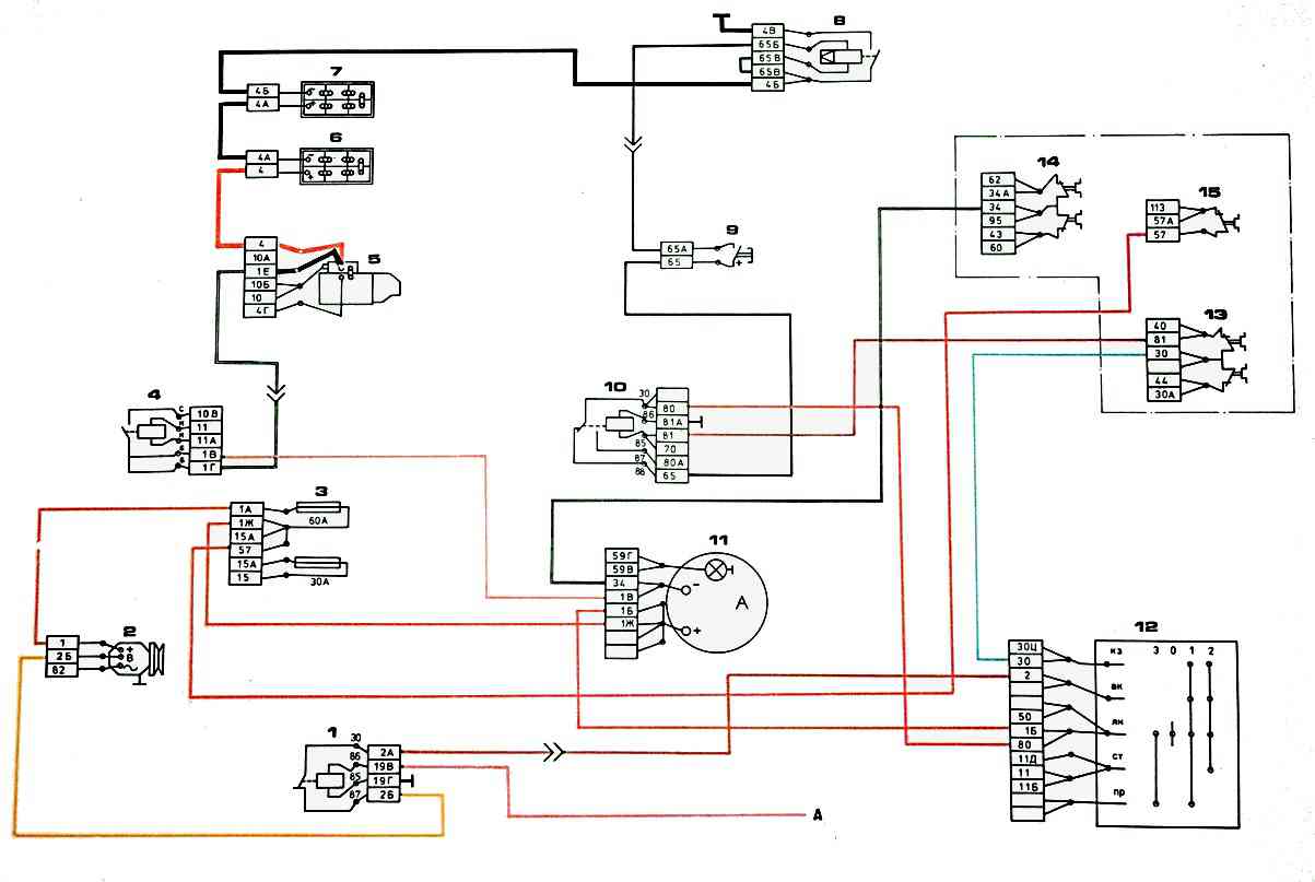
Power supply system diagram: 1 – relay for switching on the generator excitation winding; 2 – generator; 3 – fuse block; 4 – starter relay; 5 – starter; 6, 7 – batteries; 7 – ground switch; 9 – button for remote shutdown of the battery mass; 10 – heater motor relay; 11 – ammeter; 12 – instrument and starter switch; 13, 14 – fuses (7.5 A); 15 – fuses (10 A); A – to the thermal relay of the electric torch device
Switches, switches, relays, fuses, connection panels and plug connections belong to the group of switching equipment and are included in all systems.
On the electrical diagrams, next to the digital designation of the wires, their color is indicated in letters: B - white, G - blue, Zh - yellow, 3 - green, K - red, KCh - brown, O - orange, P - pink, C - grey, F - violet. H - black.
The sources of electricity are two batteries 6 connected in series and a generator set 2 connected in parallel with the batteries.
The negative terminal of the batteries is connected to the vehicle ground via remote-controlled ground switch 7.
The battery charging circuit from the generator set is protected by a 3 x 60 A fuse.
Relay 1 is introduced into the circuit, through which the excitation winding of the generator set is connected to the power source.
When starting the engine using an electric torch device, voltage is supplied to the coil of relay 1, which opens all freely closed contacts and blocks the generator set for the period of operation of the electric torch device.
In addition, the circuit provides for blocking the switching off of the mass of the batteries when the generator is running, since otherwise, when the batteries are disconnected, the generator set may fail.
For this purpose, button 8 for remote switching on the ground is connected to the power source through the normally closed contacts of the heater electric motor relay.
When the switch key 13 of devices and the starter is in position “0”, power to button 8 is carried out through the circuit: “+” batteries - starter terminals 5 - relay 4 of starter - ammeter 10 - switch 13 of devices and starter - relay 9 of electric heater motors — button 8 — winding of ground switch 7 — “—” batteries.
When you press button 8, switch 7 is activated and connects or disconnects the “—” batteries with the ground of the vehicle.
When the instrument and starter switch key is turned to position “1” or “2”, voltage is applied to the coil of relay 9, which opens its normally closed contacts and breaks the power circuit of the remote power switch button.
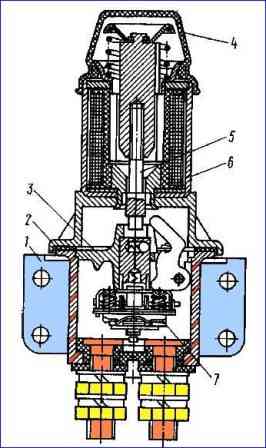
The VK 860-B mass switch is installed on the front bracket of the battery box and consists of an electromagnet, a housing with contact part and manual activation device with a protective cover (Fig. 2).
Disconnecting the batteries with button 8 is only possible when the instrument switch and starter switch are turned to the “O” position, i.e. when the generator set is disconnected from the electrical system.

")
")
")
")
")