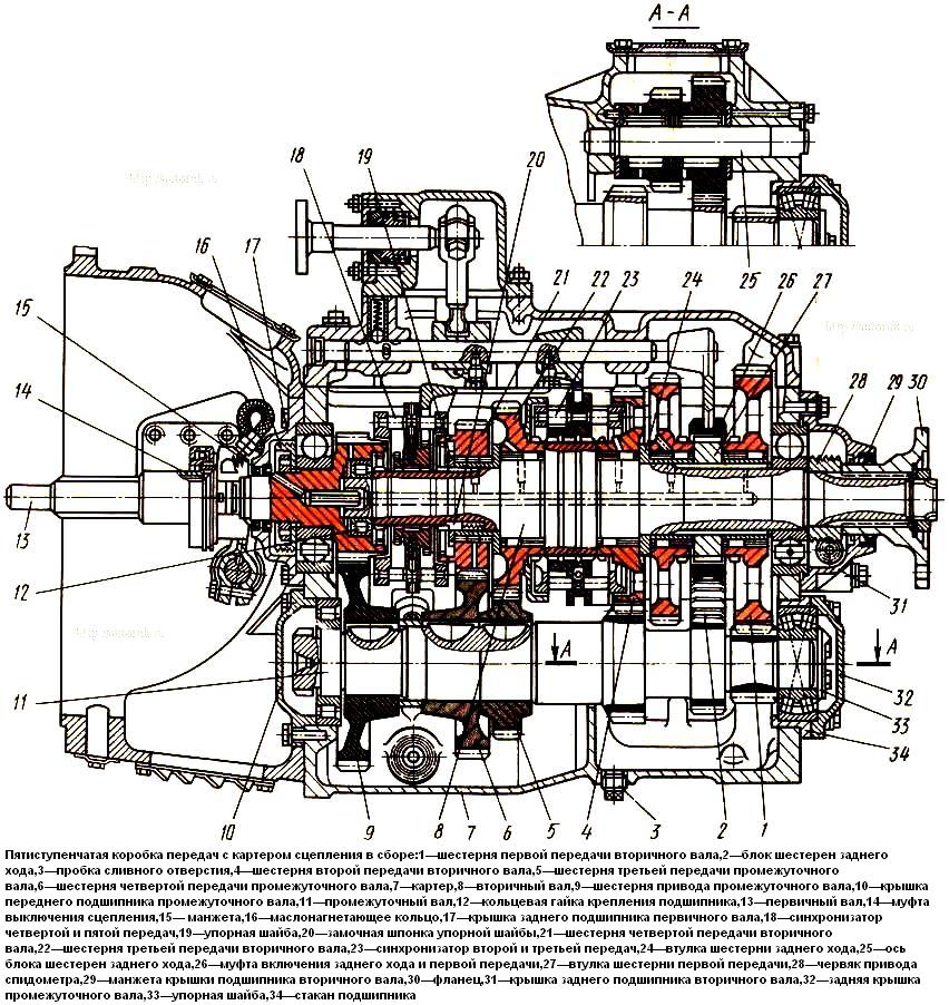
Kamaz car gearbox
For cars of the KamAZ family, the installation of gearboxes of two modifications is provided: five-speed and ten-speed
Manual five-speed gearbox. It has five forward gears and one reverse gear.
The gearbox is equipped with two inertia-type synchronizers for engaging second and third, fourth and fifth gears.
Gears in all gears, except for first gear and reverse gear, are helical, constant mesh.
The gear ratios of the box are as follows:
- - 1 - 7.82;
- - II - 4.03;
- - III - 2.5;
- -IV—1.53;
- -V- 1,0;
- - ZX -7.38.
The lubrication system is combined. All parts are splash lubricated.
In addition, oil is forcibly supplied to the gear bearings from the pumping device.
Gearbox control - mechanical with remote drive.
The gearbox is bolted to the clutch housing.
The upper studs are screwed into the clutch housing, the lower studs are screwed into the gearbox housing.
It consists of a crankcase 7 (Fig.), primary 13, secondary 8 and intermediate 11 shafts with gears and bearings assy, reverse gear block 2, gear shift mechanism, covers 10, 17, 31, 32 and bearings.
The gearbox housing is cast from gray cast iron and serves to mount all shafts and bearings.
The front and rear ends of the crankcase are machined and designed: the front one is for installing the clutch housing, the cover 17 of the rear bearing of the input shaft and the cover 10 of the front bearing of the intermediate shaft; rear - for installing cover 31 of the rear bearing of the secondary shaft and glass 34 of the rear bearing of the intermediate shaft.
In the front and rear ends, two upper and two lower holes are bored in pairs in a line for installing the input shaft rear bearing and the output shaft rear bearing, the front bearing and cup 34 of the intermediate shaft rear bearing.
Two holes are bored in the rear end and in the bulkhead of the crankcase to install the axis 25 of the reverse gear block.
The upper machined end of the crankcase is closed by a cover, which is also the body of the gear shift mechanism.
In the internal cavity of the crankcase in the front part of the left wall, an oil accumulator is cast, where, when the gears rotate, oil is thrown in and, through drilling in the front wall of the crankcase, enters the cavity of the input shaft rear bearing cover and onto the oil injection ring.
In the upper right part of the rear wall there is an oil pocket, where the oil is thrown by the rotation of the gears.
From the oil pocket, oil through drilling in the crankcase wall enters the cavity of the cover of the rear bearing of the secondary shaft to lubricate the worm pair of the speedometer drive.
On the left and right sides of the crankcase there are hatches for installing power take-offs.
Hatches are closed with lids. Permissible power take-off of 22.06 kW from each hatch.
A plug 3 is screwed in from the bottom of the crankcase, and a plug with a magnet is screwed in from the bottom right.
Above the plug with a magnet there is a filler hole closed by a plug with an oil level indicator.


