The all-mode engine crankshaft speed regulator is located in the camber of the high-pressure fuel pump housing and is driven by its cam shaft;
- designed to automatically maintain any speed limit from minimum to maximum
The operation of the regulator is based on the use of centrifugal forces.
For example, if there is additional resistance to the movement of the car (on an uphill slope), the crankshaft rotation speed will decrease and the speed of the car will fall.
To maintain them at a given level, it is necessary to increase the engine torque.
This can be achieved by increasing the amount of fuel injected into the engine cylinders.
The all-mode regulator senses a decrease in shaft speed and automatically increases the fuel supply by the high-pressure pump, due to which the vehicle speed is restored to the set value.
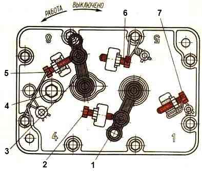
Top cover of all-mode speed controller: 1 - fuel supply control lever (regulator); 2 - minimum rotation speed limit bolt; 3 - stop lever; 4 - filler plug; 5 - bolt for regulating the starting feed frequency; 6 - bolt for limiting the travel of the stop lever; 7 - bolt for limiting maximum rotation speed
In a similar way, the all-mode regulator changes the fuel supply when the engine load decreases, only in this case the control action of the regulator is reduced to reducing the amount of fuel injected.
As a result, when the load on the engine decreases, the speed of movement decreases and is brought to a given level.
The crankshaft rotation speed maintained by the regulator at full diesel power is called the nominal speed.
It corresponds to the position of lever 1 (Fig.) for controlling the regulator when resting on bolt 7.
If the load is removed in this position of the lever, the diesel engine will develop maximum idle speed.
By moving the governor control lever clockwise, you can achieve the minimum idle speed. This corresponds to the position of the lever when resting on bolt 2.
Limiting the maximum crankshaft speed is caused by the need to protect the engine from damage due to excessive loads, and limiting the rotation speed too low is due to deterioration of fuel supply and mixture formation, which can cause a sudden engine stop.
The all-mode speed controller (Fig. 2) is designed as follows.
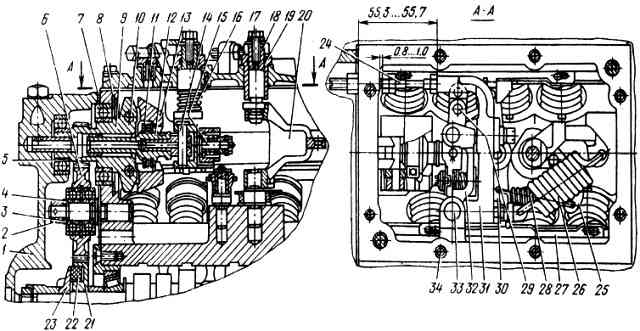
Rotation speed regulator: 1 - rear cover; 2 - nut; 3 - washer; 4 - bearing; 5 - adjusting gasket; 6 - intermediate gear; 7 - gasket for the rear cover of the regulator; 8 - retaining ring; 9 - weight holder; 10 - load axis; 11 - thrust bearing; 12 - coupling; 13 - cargo; 14 - finger; 15 - corrector; 16 - return spring of the stop lever; 17- bolt; 18 - bushing; 19 - ring; 20 - regulator spring lever; 21 - drive gear; 22 - drive gear block; 23 - drive gear flange; 24 - fuel supply adjusting bolt; 25 - starting spring lever; 26 - regulator spring: 27 - rack; 28 - starting spring; 29 - pin; 30 - rack lever; 31 - regulator lever; 32 - load clutch lever; 33 - axis of the regulator levers; 34 - bolt securing the top cover
The regulator is installed in the camber of the high pressure fuel pump housing.
The drive gear 21 of the regulator is installed on the cam shaft of the pump, rotation of which is transmitted through rubber blocks 22.
The driven gear is integral with the holder of 9 weights, rotating on two ball bearings.
When the holder rotates, the weights 13, swinging on the axes 10, diverge under the action of centrifugal forces and move the coupling 12 through the thrust bearing 11.
The clutch, resting against pin 14, in turn moves the load clutch lever 82.
Lever 32 is fixed at one end to the axis 33, and the other is connected through a pin to the rack 27 of the fuel pump.
A lever 31 is attached to the axis 33, the other end of which moves all the way to the fuel supply adjusting bolt 24.
Lever 32 transmits force to lever 31 through corrector 15.
Lever 1 of the fuel supply control (Fig. 1) is rigidly connected to lever 20 (see Fig. 2).
A spring 26 is attached to the levers 20, 31, a starting spring 28 is attached to the levers 25, 30.
During operation of the regulator in a certain mode, the centrifugal forces of the loads are balanced Ensured by spring force 26.
When the speed of rotation of the crankshaft of the regulator increases, overcoming the resistance of spring 26, the weights move the lever 32 of the regulator with the fuel pump rack - the fuel supply decreases.
When the crankshaft rotation speed decreases, the centrifugal force of the loads decreases, and the regulator lever 32 with the fuel pump rack moves in the opposite direction under the action of the spring force - the fuel supply and the crankshaft rotation speed increase
The fuel supply is turned off by turning stop lever 3 (Fig. 1) all the way to bolt 6, while lever 3, overcoming the force of spring 26 (Fig. 2), will turn levers 31 and 32 through pin 29; the rack will move until the fuel supply is completely turned off.
When the force is removed from the stop lever, under the action of the spring, the lever will return to the working position, and the starting spring 16 through the lever 30 will return the fuel pump rack necessary for starting

")
")
")
")
")