All parts of the connecting rod and piston group are divided into categories and individually selected for each other
Tables of size groups of pistons, block cylinders, pins and connecting rods, as well as mating sizes in the tables at the bottom of the article
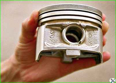
The designation “406” on the piston indicates that it is intended for the ZMZ-4062 engine.
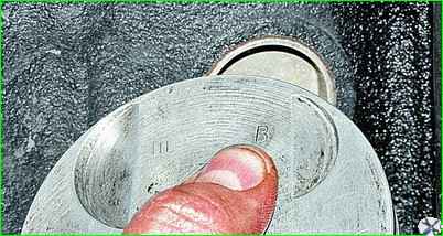
Two designations are stamped on the piston bottom.
According to the letter painted on the new block, the piston is selected to the cylinder.
When repairing with cylinder boring, the required clearances are ensured during the boring and honing process for pre-purchased pistons of repair size.
The Roman numeral indicates the required finger group.
The diameters of the holes in the piston bosses, the connecting rod head and the outer diameters of the piston pin are divided into four groups, marked with paint: I – white, II – green, III – yellow, IV – red.
On the fingers, the group number is indicated by paint on the inner surface or ends.
It must match the group indicated on the piston.
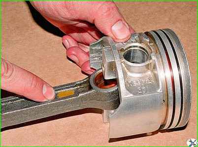
On the connecting rod, the group number is also indicated by paint.
It must either match or be adjacent to the group finger.
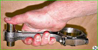
The pin, lubricated with engine oil, should move with little effort in the connecting rod head, but not fall out of it.
Heat the piston to a temperature of 60–80°C.
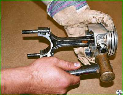
Insert the connecting rod head between the piston bosses and press in the lubricated piston pin.
If there is no device, you can press the pin with a copper or regular hammer, through a soft metal mandrel, holding the piston suspended.
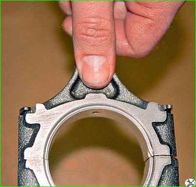
After assembly, the protrusion on the lower end of the connecting rod should be on the same side as the “FRONT” inscription on the piston.
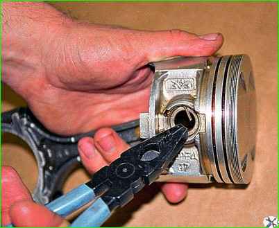
Secure the piston pin on both sides with retaining rings.
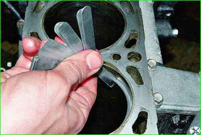
Checking the piston rings.
Compression rings installed in the cylinder to a depth of 20–30 mm should have a gap in the lock of 0.3–0.6 mm, and an oil scraper gap of 0.5–1 mm.
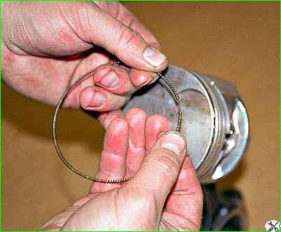
Put the rings on the piston.
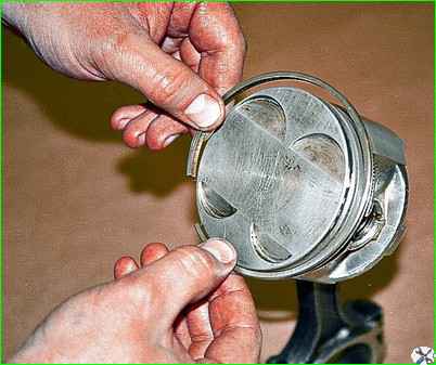
Having expanded the lock of the oil scraper ring expander, we put it on the piston into the lower groove and close the lock.
Put the oil scraper ring on the expander.
The angle between the locks of the ring and the expander with a one-piece ring is 45°, with a split ring – 90°.
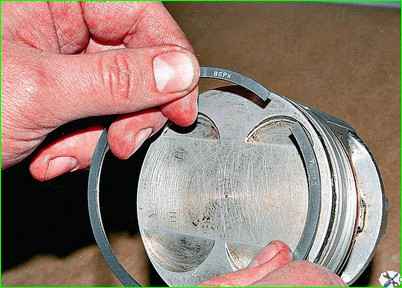
Place the lower compression ring with the inscription “TOP” on the piston bottom.
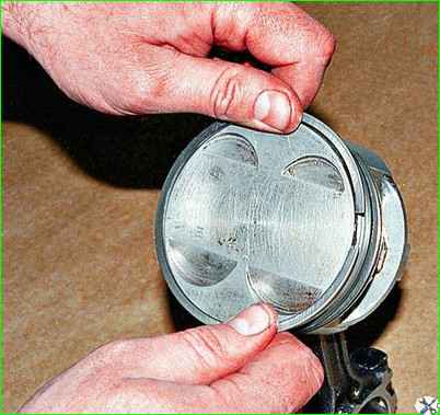
The last thing to do is put on the upper compression ring.
Table 1.
Repair increase - Group designation - Piston diameter (skirt), mm - Cylinder diameter, mm:
Nominal:
- - A - 92,000-91,988 - 92,036-93,024
- - B - 92,012-92,000 - 92,048-92,036
- - B - 92.024-92.012 - 92.560-92.048
- - G - 92.036-92.024 - 92.072-92.060
- - D - 92.018-92.036 - 92.084-92.072
0.5 :
- A - 92,500-91,488 - 92,536-92,524
- B - 92.512-92.500 - 92.548-92.536
- B - 92.524-92.512 - 92.560-92.548
- G - 92.536-92.524 - 92.572-92.560
- D - 92.548-92.536 - 92.584-92.572
1.0:
- A - 93,000-92,988 - 93,036-93,024
- B - 93,012-93,000 - 93,048-93,036
- B - 93.024-93.012 - 93.060-93.048
- G - 93.096-93.024 - 93.072-93.060
- D - 93.048-93.036 - 93.084-93.072
Pins, pistons and connecting rods
Diameter of the pin, mm - Diameter of the hole in the piston boss, mm - Diameter in the connecting rod bushing, mm - Marking of the pin and connecting rod - Marking of the piston:
- 22.0000-21.9975 - 22.0000-21.9975 - 22.0070-22.0045 - white - I
- 21.9975-21.9950 - 21.9975-21.9950 - 22.0045-22.0020 - green - II
- 22.9950-21.9925 - 21.9950-21.9925 - 22.0020-21.9995 - yellow - III
- 21.9925-21.9900 - 21.9925-21.9900 - 21.9995-21.5970 - red - VI


