Open the cover of diagnostic connector 2 (Fig. 1) and close contacts 10 and 12 (technological jumper plug)
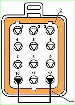
Turn on the ignition and observe the diagnostic lamp on the instrument cluster.
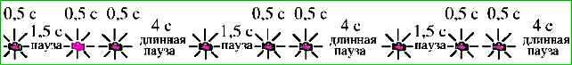
The diagnostic subsystem should issue code 12 three times in a row (Fig. 2):
- - one lamp on (0.5 s) - pause (1.5 s) - two lamp on - long pause (4 s);
- - one lamp on (0.5 s) - pause (1.5 s) - two lamp on - long pause (4 s);
- - one lamp switch on (0.5 s) - pause (1.5 s) - two lamp switches on - long pause (4 sec).
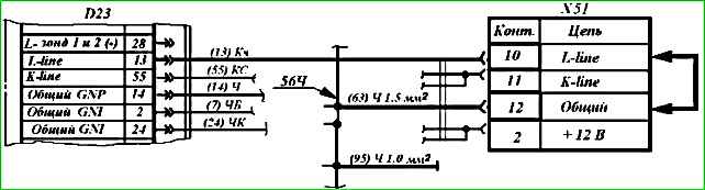
If code 12 is missing, check the diagnostic circuit for an open circuit or lack of contact in the wire connections according to the diagram (Figure 3) in the following order (D2313 - 1ЗКч - Х5110 - jumper - Х5112 - 6ЗЧ- 56Ч- 95Ч - “ground”).
If the indicated circuit is working, then control unit D23 needs to be replaced.
Record the fault codes recorded in the memory of the electronic unit using the diagnostic lamp.
If there are no fault codes in the memory, the lamp will display code 12 (see Fig. 2).

If there is a fault code, for example 131 (Fig. 4), or several codes that will be repeated three times each, find and eliminate the corresponding faults
Decoding of fault codes is given in the table:
Fault codes for the control system with the Mikas 7.1 control unit
- 13 - Low signal level of the mass air flow sensor
- 14 - High signal level of the mass air flow sensor
- 15 - Low signal level of the absolute pressure sensor
- 16 - High signal level of the absolute pressure sensor
- 17 - Low signal level of incoming air temperature sensor
- 18 - High signal level of incoming air temperature sensor
- 21 - Low signal level of the coolant temperature sensor
- 22 - High signal level of the coolant temperature sensor
- 23 - Low signal level of the throttle position sensor
- 24 - High signal level of the throttle position sensor
- 25 - Low voltage level of the on-board network
- 26 - High level of on-board network voltage
- 27 - Malfunction of the crankshaft position sensor (synchronization)
- 28 - Same
- 29 - > >
- 31 - Low signal level of the first CO corrector
- 32 - High signal level of the first CO corrector
- 33 - Low signal level of the second CO corrector
- 34 - High signal level of the second CO corrector
- 35 - Low signal level of the first oxygen concentration sensor
- 36 - High signal level of the first oxygen concentration sensor
- 37 - Low signal level of the second oxygen concentration sensor
- 38 - High signal level of the second oxygen concentration sensor
- 41 - First knock sensor circuit malfunction
- 42 - Second knock sensor circuit malfunction
- 43 - Exhaust gas recirculation valve signal low
- 44 - Exhaust gas recirculation valve signal high
- 45 - Low signal level of the canister purge valve
- 46 - High signal level of the canister purge valve
- 47 - Low power steering signal
- 48 - Power steering signal high
- 51 - Control unit 1 malfunction
- 52 - Control unit 2 malfunction
- 53 - Crank position sensor malfunction that shaft (synchronization)
- 54 - Malfunction of the camshaft position sensor (phase)
- 55 - Vehicle speed sensor malfunction
- 61 - Unauthorized restart of the control unit
- 62 - Control unit RAM malfunction
- 63 - Control unit ROM malfunction
- 64 - Failure to read non-volatile memory of the ECU
- 65 - Failure to write non-volatile memory of the ECU
- 66 - Malfunction when reading the identification code of the control unit
- 67 - Immobilizer error
- 68 - Same
- 69 - > >
- 71 - Low idle speed
- 72 High idle speed
- 73 Rich mixture when adjusted by the first oxygen concentration sensor
- 74 Lean mixture when adjusted using the first oxygen concentration sensor
- 75 Rich mixture when adjusted by the second oxygen concentration sensor
- 76 Lean mixture when adjusted using the second oxygen concentration sensor
- 79 Malfunction when controlling EGR by SEGR
- 81-84 Maximum offset of the ignition timing of the knock adjustment in cylinders 1 - 4
- 9 1-94 Malfunction in ignition circuit 1 - 4 (short circuit)
- 99 High voltage driver fault
- 131 Injector 1 fault (short circuit)
- 132 Injector 1 malfunction (break)
- 133 Injector 1 fault (short circuit to ground)
- 134 Injector 2 fault (short circuit)
- 135 Injector 2 malfunction (break)
- 136 Injector 2 fault (short circuit to ground)
- 137 Injector 3 fault (short circuit)
- 138 Injector 3 malfunction (break)
- 139 Injector 3 fault (short circuit to ground)
- 141 Injector 4 fault (short circuit)
- 142 Faulty injector 4 (break)
- 143 Faulty injector 4 (short circuit to ground)
- 167 Fuel pump relay circuit malfunction (short circuit)
- 168 Malfunction u1094 of the fuel pump relay circuit (open)
- 169 Fuel pump relay circuit malfunction (short circuit to ground)
- 171 Recirculation valve circuit malfunction (short circuit)
- 172 Recirculation valve circuit malfunction (open)
- 173 Recirculation valve circuit malfunction (short circuit)
- 174 Canister purge valve circuit malfunction (short circuit)
- 175 Canister purge valve circuit malfunction (open)
- 176 Canister purge valve circuit malfunction (short circuit to ground)
- 177 Main relay circuit malfunction (short circuit)
- 178 Main relay circuit malfunction (open)
- 179 Main relay circuit malfunction (short circuit to ground)
- 181 Diagnostic lamp circuit malfunction (short circuit)
- 182 Diagnostic lamp circuit malfunction (open)
- 183 Diagnostic lamp circuit malfunction (short circuit to ground)
- 184 Tachometer circuit malfunction (short circuit)
- 185 Tachometer circuit malfunction (open)
- 186 Tachometer circuit malfunction (short circuit to ground)
- 191 A/C relay circuit malfunction (short circuit)
- 192 A/C relay circuit malfunction (open)
- 193 A/C relay circuit failure (short to ground)
- 194 Cooling fan relay circuit malfunction (short circuit)
- 195 Cooling fan relay circuit malfunction (open)
- 196 Cooling fan relay circuit malfunction (short to ground)
- 231-234 Malfunction in ignition circuit 1 -4 (open)
- 241-244 Malfunction in ignition circuit 1 - 4 (short circuit to ground)
- 251 Malfunction of the mass air flow sensor burning circuit (short circuit)
- 252 Malfunction of the mass air flow sensor burning circuit (open)
- 253 Malfunction of the burning circuit of the mass air flow sensor (short circuit to ground)
Microprocessor electronic control unit MIKAS 5.4.209.3763.004 provides:
- 1) formation of electric current pulses for operation of ignition coils with an optimal ignition timing
- 2) generation of electric current pulses for the operation of the solenoid valve of the forced idle economizer (EFS);
- 3) ensuring the operation of the entire system in backup mode (in the event of failure of individual elements of the system);
- 4) diagnostics of system faults
The microprocessor ignition system and EPHH operate as follows.
When the ignition is turned on, the warning light on the instrument panel lights up.
At this time, the microprocessor operates in self-diagnosis mode.
At the end of this mode, the warning lamp goes out if no malfunction is detected, or remains on if a malfunction is detected.
If the warning light goes out, this means that the system is operational and ready for operation.
When the engine crankshaft is cranked by the starter, the control unit, based on signals from the position sensor, generates electric current pulses to the ignition coils to operate the spark plugs in accordance with the operating order of the engine cylinders 1-3-4-2.
To determine the optimal ignition timing, the unit uses data from all sensors and data stored in its memory.
The block continuously adjusts the output data based on changing sensor data.
The block also controls the operation of the EPH system.
This system cuts off the fuel supply when the vehicle is operating in forced idling mode when the engine is braking, thereby ensuring fuel savings and reducing the emission of toxic substances into the atmosphere
In addition to online monitoring of the engine condition, the unit can ensure engine operation even if most sensors fail.
For this purpose, a backup program is stored in the memory of the control unit, which allows, in the event of a sensor failure, to maintain the operation of the engine with slightly suboptimal characteristics, which makes it possible to get to the garage or car service station under its own power.
At the same time, a warning lamp lights up on the instrument panel, which will remain on continuously until the malfunction is eliminated.
The failure of only one sensor - synchronization - leads to a complete stop of the engine.
The unit's reserve mode allows you to operate the vehicle until repairs are carried out.
At the same time, throttle response deteriorates, toxicity worsens, and fuel consumption may increase.
Fault codes for the microprocessor ignition system of the ZMZ-5061 and ZMZ-4063 engines with the Mikas 5.4 control unit
Code - Description of the malfunction
- 12 Diagnostic circuit performance
- 21 Low signal level of the coolant temperature sensor
- 22 High signal level of the coolant temperature sensor
- 25 Low voltage level of the vehicle's on-board network
- 26 High voltage level of the vehicle's on-board network
- 51 Control unit malfunction
- 53 Synchronization sensor malfunction
- 61 Unauthorized restart of the control unit
- 62 Loss of information in the control unit RAM
- 63 ROM failure
- 64 Malfunction when reading non-volatile memory of the control unit
- 65 Malfunction when writing to the non-volatile memory of the control unit
- 182 Diagnostic lamp circuit malfunction (open)

")
")
")
")
")