Clean the piston heads and grooves for piston rings from carbon deposits
Pistons in the cylinders of the block must be installed group by group, in accordance with the table
Pistons according to the outer diameter of the skirt and cylinders according to the internal diameter are sorted into three size groups and marked with the letters - A, B, C.
A letter indicating the size group of the cylinder diameter is painted on the outer surface of the cylinder block on the right, opposite each cylinder.
Size groups of cylinder diameters are determined during the manufacture of the cylinder block.
When repairing a used engine with worn cylinders, it is necessary to re-measure the cylinder diameters and determine their group.
Cylinder diameters should be measured at a temperature of plus 20±3˚C.
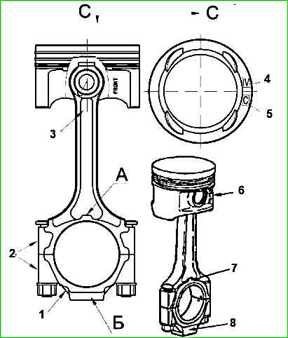
Pistons are marked with letters on the bottom (Figure 1).
The largest diameter of the piston skirt is located in a plane perpendicular to the piston pin axis at a distance of 47.5 mm from the piston bottom.
Measure the piston skirt diameters at a piston temperature of plus 20 ± 3 °C.
Pins by outer diameter, connecting rods and pistons by pin hole diameter are sorted into four size groups, which are marked with paint or Roman numerals (Table 1).
The size group of the connecting rod hole for the pin is marked with paint on the rod in the area of the piston head.
The piston hole group is designated by Roman numerals stamped on its bottom (Figure 1), and the pin by Roman numerals stamped on the end.
The connecting rod must be assembled with a pin of the same size group.
If the non-parallelism of the axes of the holes of the piston and crank heads exceeds the maximum permissible value, the connecting rod is deformed and must be replaced.
If the hole in the connecting rod bushing for the pin is worn beyond the acceptable level, it is necessary to replace the bushing, make a groove in the bushing for the oil channel and machine the hole in the bushing for the pin.
Before installing a new bushing, measure the diameter of the connecting rod mounting hole - if the hole wears more than acceptable, the connecting rod should be rejected.
Make measurements of pistons, pins and connecting rods at a temperature of 20±3 °C.
Connecting rods are sorted into three groups by weight and marked with paint on the connecting rod cover (Figure 1). Marking color:
- - white - corresponds to the mass of the connecting rod 900-905 g;
- - green - 895-900 g;
- - yellow - 890-895
Size groups of pistons and cylinders of the block
Group A:
- - piston diameter (skirt) - 95.488 - 95.500 mm;
- - cylinder diameter - 95.536 - 95.548 mm
Group B:
- - piston diameter (skirt) - 95.500 - 95.512 mm;
- - cylinder diameter - 95.548 - 95.560 mm
Group C:
- - piston diameter (skirt) - 95.512 - 95.524 mm;
- - cylinder diameter - 95.560 - 95.572 mm
Group AI repair increase 0.25:
- - piston diameter (skirt) - 95.738 - 95.750 mm;
- - cylinder diameter - 95.786 - 95.798 mm
Group BI repair increase 0.25:
- - piston diameter (skirt) - 95.750 - 95.762 mm;
- - cylinder diameter - 95.798 - 95.810 mm
CI group repair increase 0.25:
- - piston diameter (skirt) - 95.762 - 95.774 mm;
- - cylinder diameter - 95.810 - 95.822 mm
Group AII repair increase 0.5:
- - piston diameter (skirt) - 95.988 - 96.000 mm;
- - cylinder diameter - 96.036 - 96.048 mm
Group BII repair increase 0.5:
- - piston diameter (skirt) - 96,000 - 96,012 mm;
- - cylinder diameter - 96.048 - 96.060 mm
Group CII repair increase 0.5:
- - piston diameter (skirt) - 96.012 - 96.024 mm;
- - cylinder diameter - 96.060 - 96.072 mm
Size groups of pins, pistons and connecting rods
Finger diameter - 21.9935—21.9960 mm:
- - holes in the piston boss - 21.9975—22.0000 mm;
- - holes in the connecting rod bushing - 22.0045—22.0070 mm;
- - connecting rod marking - white;
- - piston and pin marking - “I”
Finger diameter - 21.9910—21.9935 mm:
- - holes in the piston boss - 21.9950—21.9975 mm;
- - holes in the connecting rod bushing - 22.0020—22.0045 mm;
- - connecting rod marking - green;
- - piston and pin marking - “II”
Finger diameter - 21.9885—21.9910 mm:
- - from hole in the piston boss - 21.9925—21.9950 mm;
- - holes in the connecting rod bushing - 21.9995—22.0020 mm;
- - connecting rod marking - yellow;
- - piston and pin marking - “III”
Finger diameter - 21.9860—21.9885 mm:
- - holes in the piston boss - 21.9900—21.9925 mm;
- - holes in the connecting rod bushing - 21.9970—21.9995 mm;
- - connecting rod marking - red;
- - piston and pin marking - “IV”
For installation on the engine, you should take connecting rods of the same weight group.
Pistons are not sorted by weight.
Check the difference in mass of the selected sets of piston, pin, connecting rod and rings, which should not exceed 10 g.
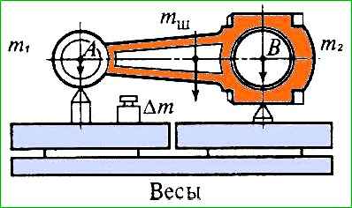
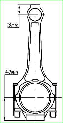
If there is a greater difference in the masses of the sets, in order to eliminate increased engine vibrations, the mass of the sets should be equalized; to do this, remove the metal from the connecting rods of heavier sets from the weight bosses of the piston or crank heads, depending on the mass of the heads, to a size not less than that shown in the figure 2.
When removing material, the mass of the connecting rod heads should not exceed the following limits: piston (m 1) - 211-217 g, crank (m 2) - 679-688 g.
Lubricate the piston pin with engine oil and insert it into the holes of the piston and connecting rod.
Connecting rods and pistons, when assembled with a piston pin, must be oriented as follows: the inscription “FRONT” located on the outside of the pin boss and the protrusion “A” on the crank head of the connecting rod must be directed in the same direction.
The connecting rod cover on the connecting rod must be installed so that the ledge “B” on the connecting rod cover and the ledge “A” on the crank head or the cylinder numbers stamped on the side surface of the cover and crank head or the grooves for the liners are located on one side (Figure 1 ).
Rings intended for installation in cylinders of nominal diameter are marked with yellow paint on the upper compression ring.
For installation in cylinders of the first repair size - blue, of the second repair size - green.

The thermal gap, measured at the joints placed in the cylinder (Figure 4), for new rings should be:
- - 0.25-0.45 mm at the upper compression ring;
- - 0.45-0.65 at the lower compression ring;
- - 0.30-0.55 mm for a box-shaped oil scraper ring.
For worn rings, the maximum size allowed in the lock is no more than 1.5 mm.
Place rings for measuring the thermal gap in the lock in the upper unworn part of the cylinder (from the upper edge of the cylinder to the location of the first compression ring when the piston is at TDC) or in a mandrel of the same diameter.
Pre-clean the surface of the cylinder from carbon deposits.
Installing piston rings with a smaller thermal gap at the joint will lead to convergence of the ring joint during engine operation and cylinder nadir.
Installing worn rings with a large gap will lead to a decrease in compression stroke pressure and increased oil loss.
Check the lateral clearance between the rings and the piston groove wall with a feeler gauge (Figure 5). Check the circumference of the piston at several points.
The side clearance should be 0.045-0.090 mm for new rings and pistons. For worn rings and pistons, a maximum clearance of no more than 0.15 mm is allowed.
A larger gap will lead to increased oil loss due to the “pumping” action of the rings.
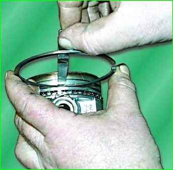
Place the piston rings onto the piston using the tool (Figure 6).
Install the lower compression ring with the inscription “TOP” (top) on the end towards the piston crown. The rings in the grooves must move freely.
Insert the pistons into the cylinders as follows:
- - orient the connecting rod-piston group so that the inscription “FRONT” on the piston boss faces the front of the cylinder block,
- - wipe the beds of the connecting rods and their covers with a napkin, wipe and insert the liners into them,
- - turn the crankshaft so that the cranks of the first and fourth cylinders take the position corresponding to BDC;
- - lubricate the bearings, piston, connecting rod journal and first cylinder with clean engine oil;
- - move the ring locks at an angle of 120° (approximately) to each other, while the joint of the spring expander should be placed opposite the lock of the oil scraper ring box before installing the ring on the piston.
It is recommended not to place the ring locks in a plane perpendicular to the axis of the finger;
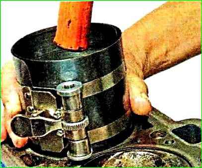
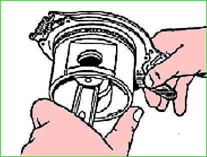
- put safety tips on the connecting rod bolts, use a special mandrel with an internal conical surface to compress the rings and insert the piston into the cylinder (Figure 7).
Before installing the piston, you should once again make sure that the numbers stamped on the connecting rod and its cover correspond to the serial number of the cylinder, check the correct position of the piston and connecting rod in the cylinder.
Pull the connecting rod by the crank head to the connecting rod journal, remove the brass tips from the bolts, and put on the connecting rod cover.
The connecting rod cap should be installed so that the numbers stamped on the cap and connecting rod, or the grooves for the liners, are on one side.
Tighten the nuts with a torque wrench to a torque of 68-75 Nm (6.8-7.5 kgcm).
Insert the piston of the fourth cylinder in the same order.
Rotate the crankshaft 180˚ and insert the pistons of the second and third cylinders.
Rotate the crankshaft several times, which should rotate easily with little effort.

")
")
")
")
")