Removal and installation of the crankshaft of the ZMZ-406 engine
Remove the oil sump and crankcase gasket
Remove the oil pump.
Remove the camshaft drive chains.

Unscrew six bolts 1 of the flywheel mounting, remove washer 2 of the flywheel bolts.
Remove flywheel 3.

Unscrew the six bolts 1 and remove the oil seal holder 2 with the rear crankshaft oil seal 3 pressed into it.
Remove the oil seal holder gasket.

If you do not need to remove the pistons from the cylinders, you don’t have to remove the cylinder head, just unscrew the nuts of the 3 connecting rod bolts, remove the caps of the 5 connecting rods and carefully push the pistons into the cylinders.
Unscrew bolts 1 and remove caps 6 of main bearings.
Since the lids are tight, knock them off with gentle blows of a hammer. Remove the upper half washers 4 of the thrust bearing.
Remove crankshaft 2 with gear and bushing 7 as an assembly.
Remove the main bearing shells and lower thrust bearing half washers from the main bearing beds and caps.
Checking and repairing the crankshaft
Rinse all parts with gasoline and dry.
Inspect the crankshaft. If it has cracks, it needs to be replaced.

Remove the plugs, rinse with gasoline and blow out the oil passages of the crankshaft with compressed air.
Tighten the plugs and tighten them to a torque of 38–42 Nm (3.8–4.2 kgcm).
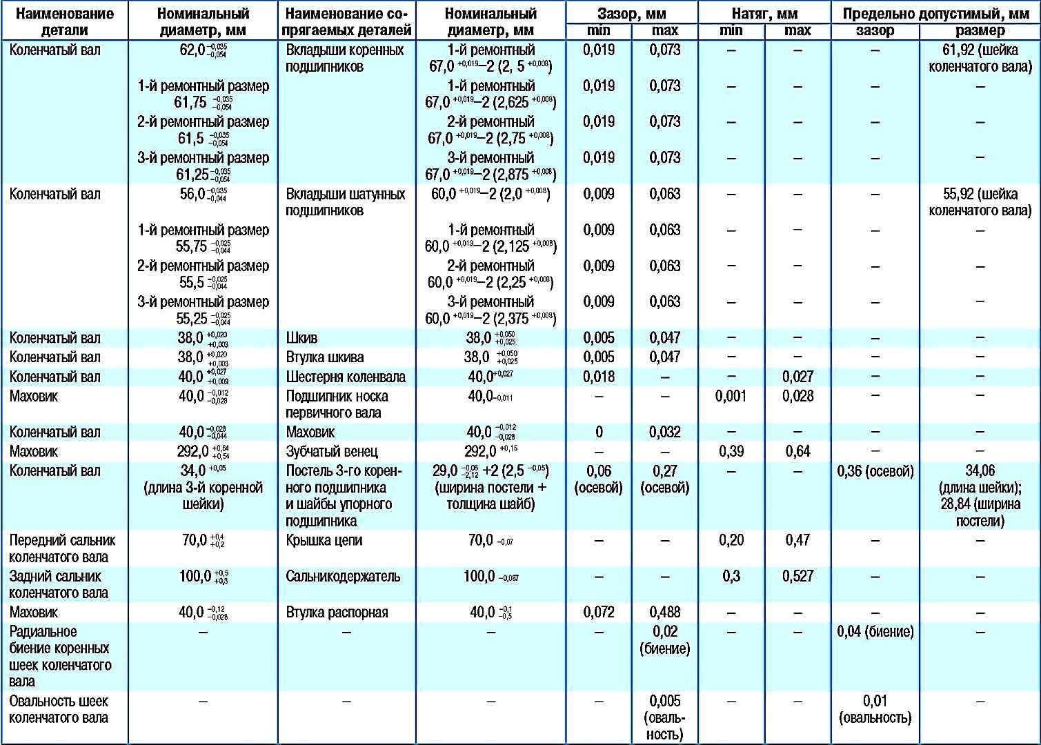
If there are minor scuffs, marks, scratches on the main and connecting rod journals, or the ovality of the journals exceeds 0.01 mm, they should be ground to the repair size.
After grinding, polish the journals. The shaft journals must be ground to one of the repair dimensions indicated in the table.
Blunt the sharp edges of the chamfers of the oil channels using an abrasive cone.
After grinding, wash the crankshaft and blow out the oil passages with compressed air.
After grinding the crankshaft journals, you need to install the main and connecting rod bearing shells of the appropriate repair size.
Inspect the main bearing shells.
If they have marks, burrs, scratches, peeling, inclusions of solid particles, etc., replace the liners.
Inspect the flywheel.
If the flywheel ring teeth are damaged, there are burrs, scratches, etc. on the surface adjacent to the clutch driven disc, replace the flywheel.
If there are cracks on the flywheel, it must also be replaced.

A closed-type input shaft toe bearing is pressed into the flywheel.
Inspect the bearing, if defects are found (large play, jamming, damage to protective rings, etc.), press it out of the flywheel.
Press in the new bearing flush with the bottom edge of the chamfer of the hole in the flywheel

Inspect the front and rear crankshaft oil seals in the chain cover (pictured) and oil seal holder.
They should not be damaged (tears, tears or excessive wear of the working edge, etc.).
Replace damaged oil seals. To do this, remove the old oil seal using a screwdriver and press in the new one.
If the vehicle has a high mileage, it is recommended to replace both oil seals when disassembling the engine.
Measure the diameters of the crankshaft main and connecting rod journals.
If the diameters of the connecting rod journals are less than 55.92 mm, the main journals are less than 61.92 mm, you need to grind the journals to the repair size.
All main or connecting rod journals must be ground, even if only one journal is smaller than the specified maximum permissible size.
Disassembling the crankshaft
Disassembly of the crankshaft is required before grinding its journals and to replace the timing sprocket.

Use a puller to compress the coupling.
If there is no puller, remove it with blows through a brass mandrel.

Using a screwdriver, remove the rubber ring, having previously knocked the key out of the shaft slot.

We press the sprocket with a brass mandrel and, using a screwdriver, remove the sprocket key.

After grinding the crankshaft journals with a bolt with a “14” head and locked nuts, unscrew the plugs.
The channels for the passage of oil in the crankshaft are thoroughly cleaned of deposits and abrasive residues.
We wash the crankshaft channels with kerosene, gasoline or diesel fuel and blow with compressed air.

Screw the oil channel plugs into place

We use a beard to open the edges of the plugs
Assemble the shaft in reverse order. We begin pressing the sprocket and coupling by installing the corresponding keys into the groove of the crankshaft.

Installing the crankshaft
Installation is carried out in the reverse order of removal, taking into account the following:
In the main bearing caps, liners are installed without grooves, and in the bed - with grooves.
The upper half washers of the thrust bearing are installed in the grooves of the bed of the 3rd main bearing with an antifriction layer to the crankshaft cheek, the lower ones - together with the cover, while the antennae of the half washers should fit into the grooves of the cover.
Before installation, lubricate the crankshaft main and brass journals, main bearing shells and thrust bearing half-washers with engine oil.
Tighten the bolts of the main bearing caps to a torque of 100–110 Nm (10–11 kgf m).
Tighten the flywheel mounting bolts to a torque of 72–80 Nm (7.2–8.0 kgf m).
Before attaching the connecting rods, rotate the crankshaft. It should rotate easily, without jamming.
Nominal and maximum permissible dimensions and fit of mating parts of the crankshaft
Nominal and maximum permissible dimensions of the mating parts of the crankshaft of the ZMZ-4061, ZMZ-40522 and ZMZ-40524 engines

")
")
")
")
")