The pneumatic system of bus brakes consists of a compressor, pneumatic devices and pipelines
The diagram of the pneumatic drive of the brake system is shown in Figure 1.
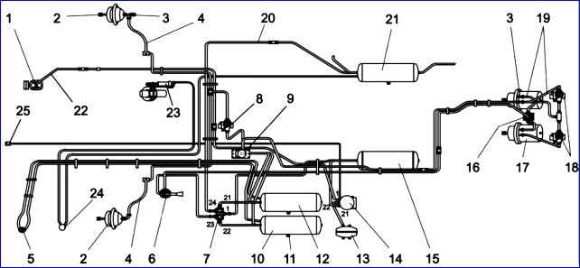
In order to prevent failures of the pneumatic devices of the brake system from clogging during the initial period of operation, strainers can be installed at the inlet of the brake valve, dryer, four-circuit safety valve and modulators.
The PAZ-32053-07 bus uses a single-cylinder piston-type air-cooled compressor
The compressor is driven by the drive gear of the high pressure fuel pump.
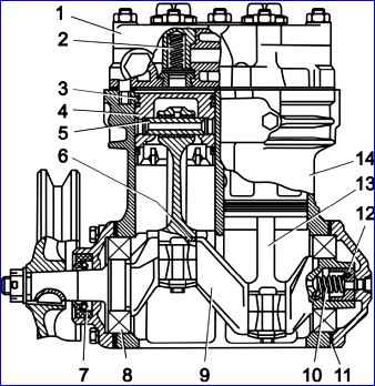
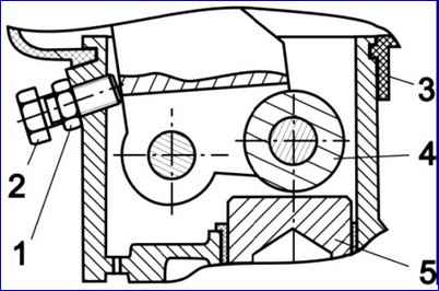
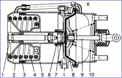
On the PAZ-4234 bus, both a two-cylinder (Fig. 2) and a single-cylinder compressor can be used. In both cases, the compressor has an air-cooled cylinder block and a water-cooled cylinder head.
The compressor is driven by a belt from the crankshaft pulley. The belts are tensioned by a special mechanism.
Oil from the lubrication system is supplied through a hose to the compressor crankshaft channel and to the connecting rod bearings.
Ball bearings, piston pins and cylinder walls are splash lubricated.
Oil from the compressor is drained into the engine oil sump.
When servicing the compressor, check its fastening to the bracket, the fastening of the pulley, the tension of the drive belts (PAZ-4234), the fastening of the compressor cylinder head, as well as the condition and fastening of the compressor discharge tube, hoses for supplying coolant to the cylinder head (PAZ-4234) .
The compressor drive belt on the D-245.9E2 diesel engine is tensioned by a roller through the tension mechanism.
Before tensioning, loosen the tension roller shaft locking bolt and the adjusting screw locking nut.
Then rotate the nut on the adjusting screw to move the screw together with the tension roller.
It is recommended to clean the compressor pistons and valves from carbon deposits once a year during seasonal maintenance, but no more than after 100,000 km.
Signs of a compressor malfunction are: noise and knocking, excessive heating (more than 190 °C), increased oil content in the condensate drained from the air cylinders.
Tightening the cylinder head nuts should be done evenly in the order shown in Fig. 3.
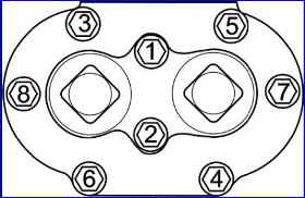
Final tightening is performed with a torque of (20-25) Nm.
It is allowed to simultaneously tighten the head nuts to the final torque.
Attention! Air leaks in the pneumatic brake system increase the duration of operation of the compressor under load and thereby reduce its service life.
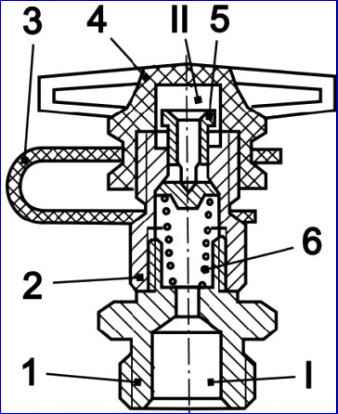
An air dryer with a built-in pressure regulator (Fig. 4) is designed to clean compressed air from moisture and contaminants, as well as to automatically maintain operating pressure in the pneumatic brake drive system.
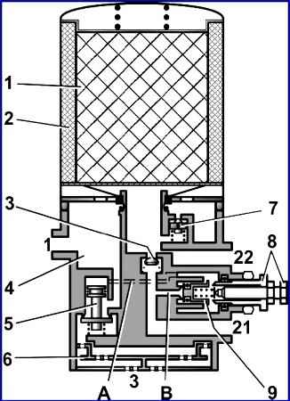
The air supplied by the air compressor passes through the ring filter 2, where it is pre-cleaned from contaminants. There, the air is cooled, and part of the moisture contained in it is collected in moisture separation chamber 4.
The air then passes through granular powder 1, where dehumidification occurs, to check valve 3, opens it and passes through outlet 21 to the four-circuit safety valve and then to the air receivers.
At the same time, an air receiver with a capacity of 5 liters is filled through the nozzle and outlet 22 to regenerate the drying element.
The air dryer has an electrically heated valve assembly, which is turned on when the key in the instrument switch is turned to position “I”. Electric heating turns on automatically at an ambient temperature of less than +10°C and turns off after heating to +30°C.
To monitor the normal operation of the dryer, you should check daily for the absence of condensation in the cylinder located after the dryer and monitor the tightness of the pneumatic drive of the brake system.
If condensation appears in the receivers, it is necessary to replace the filter element.
If there is oil in the condensate, it is necessary to repair the compressor, since oiling the desiccant powder granules sharply reduces its service life.
Attention! To prevent brake system failures, the air dryer filter cartridge should be replaced once a year, regardless of its condition before the start of the winter period of operation.
Replacing the air dryer filter element is carried out in the following order:
- Clean the surface of the dryer from dirt.
- Loosen the threaded connection of the discharge pipe from the compressor and bleed air from it.
- Unscrew the filter element cartridge by rotating counterclockwise.
- Install a new cartridge, lightly lubricating the sealing gasket with oil.
- Tighten the cartridge by hand to a torque of no more than 15 Nm.
- Tighten the threaded connection of the discharge pipe.
The four-circuit safety valve (Fig. 5) is designed to divide the supply line into two main and two additional circuits, automatically turn off one of the circuits in case of damage and preserve the supply of compressed air in undamaged circuits, as well as to preserve air in all circuits in case of damage to the supply line.
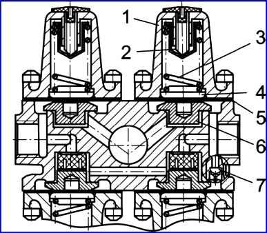
The safety valve sections are adjusted in such a way that first the main valves of the service brake system and the door drive open (in Fig. 6, sections 21, 22, 24) at a bypass pressure of (607-637) kPa, and then the parking brake valve opens. brake system (section 23) at a bypass pressure of (656-686) kPa.
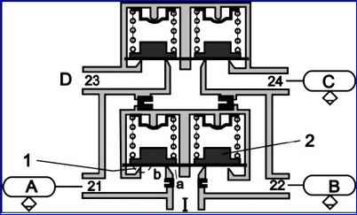
When section 21 is depressurized into it from section 23 through a specially built-in valve, compressed air is bypassed at a rate of at least 60 l/min.
After the bypass, the residual air pressure in the energy accumulators should be no more than 100 kPa (1 kgf/cm 2).
Adjusting the valve eliminates the possibility of the bus starting to move when the pneumatic system is filled with compressed air to the point that ensures braking of the bus with the required efficiency, and also eliminates the possibility of releasing the parking brake system of the bus when the pressure level in circuit 1 of the service brake system drops below the minimum level ─ less than 390 kPa (4.0 kgf/cm 2).
The parking brake manual valve is designed to control the spring energy accumulators of the parking brake system.
When the bus is moving, the crane handle is in the extreme forward position.
The crane device ensures that the handle automatically returns to the lower position when it is released. Only in the rearmost position does the handle lock xia.
To release spring energy accumulators, the handle should be pulled out in the radial direction, while the handle freely returns to the “released” position.
The quick release valve is designed to speed up the release of air from the actuators, by reducing the path traveled by compressed air during release.
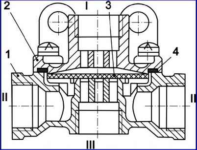
When the parking brake valve handle is in the “released” position, compressed air enters outlet “I” of the valve (Fig. 7), diaphragm 3 is pressed against the outlet seat in the housing; in this case, the edges of the diaphragm are bent and compressed air passes into terminals “II” and further into the energy accumulators.
When the pressure drops in terminal “I”, diaphragm 3, under the action of compressed air in terminals “II”, breaks away from the outlet seat in housing 1 and is pressed against the seat in cover 2, thereby blocking the passage of air into terminal “I”.
Compressed air is released into the atmosphere through terminal "III".
The brake valve is designed to control wheel brake mechanisms with a dual-circuit brake drive.
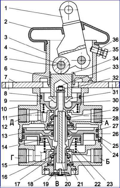
Terminals “A” and “B” of the valve (Fig. 8) are connected to the air receivers of two separate service brake drive circuits.
From terminals “G” and “D”, compressed air flows to the brake chambers. Brake signal switches are installed in the crane body.
From terminal “B”, air escapes into the atmosphere after releasing the brake pedal.
When servicing a brake valve, the attachment of the valve to the body base bracket is checked, the integrity of the protective rubber boot and the tightness of its installation are checked, and a diagnostic check is made for the correct operation of the valve.
In winter, if the tap freezes, to prevent damage to rubber and plastic parts, it is not recommended to warm the tap with an open fire.
You should use warm air or hot water for heating.
Due to the gradual disruption of the mobility of the brake valve pistons during bus operation, especially when water and oil get inside the valve on the friction surface, it is recommended to carry out a diagnostic check of the operation of the valve during TO-2.
To do this, without removing the valve from the bus, you need to connect one pressure gauge to its upper and lower sectional terminals and, pressing the brake pedal, note the pressure difference.
The pressure difference should not exceed 0.025 MPa. If this condition is not met, the crane must be repaired.
It is recommended to carry out preventive disassembly of the brake valve once every 2 years to clean, lubricate and replace rubber O-rings and worn parts.
Assembling and checking the functionality of the brake valve
- Assembly should be carried out taking into account the following requirements:
- - assembly must be carried out under conditions that exclude the possibility of abrasive dust, etc., coming into contact with the assembled parts.
- - assembly of rubber parts must be done carefully to avoid the possibility of damage. The presence of cuts, scratches and other defects on rubber parts is not allowed.
- - lubricate all rubbing surfaces of parts with a thin layer of CIATIM 221 lubricant. The use of AZMOL ZhT-72 lubricant is allowed.
- Before installing the upper piston, measure the distance “c” (Fig. 9) of the protrusion of the piston shank above the valve.
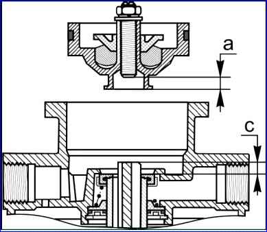
- Using the adjusting screw in the upper piston, set the distance α = (c + 0.8) mm and lock the adjusting screw.
- Install the upper piston and, if necessary, Press it with a transport clamp.
- Assemble the apparatus with the base plate and lever.
- Install the adjusting bolt all the way into the lever so that there is no gap between roller 4 and pusher 5 (Fig. 10), fix adjusting bolt 2.
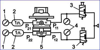
- Connect the valve to the compressed air system in accordance with the test diagram (Fig. 11).
- Move the lever three times until it stops (travel of at least 31.2 mm). When moving the lever there should be no jamming and it should quickly return to its original position.
- Apply air under pressure P11 = P12 = 0.75 MPa (7.5 kgf/cm 2) to terminals 11 and 12.
Move the lever all the way and back three times.
The pressure in terminals 21 and 22 should change from 0 to the pressure in terminals 11 and 12 and back.
- When the lever moves 4.7-7.4 mm (pusher stroke 1.9-3.0 mm), pressure should appear in pin 21.
When pressure P21 = 0.05 MPa (0.5 kgf/cm 2) is reached in outlet 21, the pressure in outlet 22 must be at least 0.025 MPa (0.25 kgf/cm 2).
In this case, the lever stroke must exceed 4.7 mm (the pusher stroke must exceed 1.9 mm).
The advance of pressure growth in terminal 21 relative to the pressure growth in terminal 22 can be maintained over the entire pressure range, but not exceed 0.025 MPa (0.25 kgf/cm 2).
The initial pressure surge in terminals 21 and 22 should not exceed 0.02 MPa (0.2 kgf/cm 2).
- When pressure P21 = 0.3 MPa (3.0 kgf/cm 2) is reached in terminal 21, the lever stroke should be (14.5-19.9) mm (pusher stroke (5 .8-8.0) mm).
- When pressure P21 = 0.75 MPa (7.5 kgf/cm 2) is reached in terminal 21, the lever stroke should be (21-27) mm (pusher stroke (8.4-10.8) mm).
- The total stroke of the lever to the stop should be (31.1-39.1) mm (pusher stroke (12.5-15.7) mm).
- When the lever moves smoothly, the pressure in terminals 21 and 22 after the initial jump should gradually increase, and when the lever is released, it should gradually decrease.
- Supply air under pressure P12 = 0.75 MPa (7.5 kgf/cm 2) to terminal 12.
Move the lever until it stops. In this case, the pressure in terminal 22 should change from 0 to 0.75 MPa (7.5 kgf/cm 2).
- Apply air under pressure P11 = 0.75 MPa (7.5 kgf/cm 2) to terminal 11.
Move the lever until it stops. In this case, the pressure in terminal 21 should change from 0 to 0.75 MPa (7.5 kgf/cm 2).
- Check the device for leaks. The tap must be sealed in any position of the lever.
The check is carried out with the lever released and pressure P11=P12 = 0.75 MPa (7.5 kgf/cm 2) in terminals 11 and 12 and with the lever pressed all the way and pressure P = 0 .75 MPa (7.5 kgf/cm 2) in terminal 11. Air leakage in each case should not exceed 8 cm 3 /min.
The brake valve drive is adjusted correctly if the full travel of the brake pedal, determined by the movement of the center of the pedal pad, is (105-117) mm.
In this case, the pedal platform should not touch the floor in the extreme pressed position, and the brake valve should be completely open. Pedal free play (18-25) mm.
The free play of the brake pedal is determined by the design of the brake valve.
If necessary (when removing and installing a tap), you can adjust the tap drive as follows:
- - by rotating the fork along the thread of the rod, align the hole in the fork with the hole in the faucet lever, which is in a free state;
- - unscrew the fork from the rod one turn and in this position install the fork pin, pin the pin and tighten the fork lock nut.
The control outlet valve (Fig. 12) is designed for connecting control and measuring instruments to the drive for the purpose of checking pressure.
The bus has two valves: one on the right front and one on the right rear brake chambers.
To connect to the valve, use hoses and measuring instruments with a union nut M16x1.5. If necessary, the valve can be installed in receivers by unscrewing the plugs from the bosses.
The condensate drain valve (Fig. 13) is designed for forced draining of condensate from the air receiver of the brake drive, and also, if necessary, for releasing compressed air from the receiver.
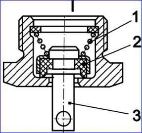
The condensate drain valve opens when you press pusher 3 up or move it in any direction.
Brake chambers are designed to operate the wheel brakes.
The brake chamber with a spring energy accumulator is designed to activate the brake mechanisms of the rear axle wheels when the service or parking brake systems are engaged.
If the seal is broken and the pressure in the parking brake system circuit decreases, air from the cavity under piston 5 through terminal “I” will escape into the atmosphere through the damaged part of the pneumatic drive, spring 4 will be released and the bus will automatically brake.
To mechanically release the rear wheels, it is necessary to unscrew screw 1 (Fig. 14) from the spring energy accumulator 68 mm from the outer surface of cylinder 2.
Attention! Before releasing the brakes, the bus should be secured against rolling away.
Attention! It is prohibited to disassemble the energy accumulator without using a special device, since there is a powerful spring inside it in a compressed state.
Attention! Before starting to operate the bus, the energy accumulators of the brake chambers should be brought into working condition; to do this, you need to fill the brake system with air, set the handle of the parking brake valve to the release position and tighten screw 1 until it stops (Fig. 14).
The auxiliary brake system consists of an engine brake 5 located in the engine exhaust pipe 1, a pneumatic cylinder 3, a control valve and pipelines.
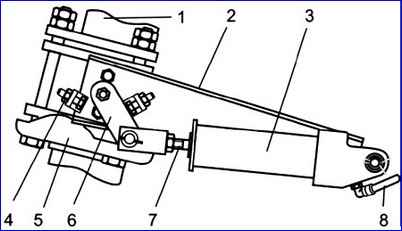
The auxiliary brake system is activated by pressing and holding the valve button located on the driver's floor to the left of the clutch pedal.
In this case, compressed air through pipelines from the air cylinder of the brake system enters pneumatic cylinder 3, which, through lever 6, moves the damper in the engine brake and thereby blocks the exhaust pipe of the muffler.
Attention! Before applying the engine brake, release the fuel control pedal.
Attention! The auxiliary braking system (engine brake) only slows down the movement, preventing the bus from gaining speed on long descents.
It is not intended for stopping a bus; it cannot be used for emergency braking or as a parking brake.
Attention! The engine brake is only used when driving on long descents with the gear engaged.
In this case, a gear must be selected in which the engine speed does not exceed the maximum permissible (2400 min -1).
When servicing the pneumatic drive of the bus brake system, the tightness of the system as a whole and its individual parts is checked. Places of strong air leakage are determined by ear, and places of weak leakage are determined using a soap emulsion.
An air leak in the service brake system is determined when the system is filled to operating pressure and the brake pedal is pressed.
In this case, the pressure drop should not exceed 0.05 MPa (0.5 kgf/cm 2) for 15 minutes and 0.05 MPa for 30 minutes with the controls in a free position.
An air leak in the parking brake system is detected when the handbrake handle is in the “Unbraked” position.
Air leakage from pipeline connections is eliminated by tightening or replacing individual connection elements.
To avoid breakage of the connecting bosses on pneumatic brake devices, the tightening torque of fittings, plugs, and nuts should not exceed (30-50) Nm.
To increase the reliability and reliability of the brake system, it is recommended to carry out preventive disassembly of the brake valve once every two years; brake chambers of rear and front brakes, safety valve; manual brake valve; quick release valve; replacement of a replacement dryer cartridge, regardless of their technical condition.
Faulty devices discovered during a control check must be repaired using repair kits and checked for operability and compliance with specifications.
The procedure for assembling and testing the devices is set out in special instructions. Their repairs are carried out by persons who have undergone the necessary training.
Attention! It is not allowed for pipelines to sag, touch them with parts and components that move and heat up during operation, or bend pipelines with a decrease in their flow area.

")
")
")
")
")