The bus is equipped with three separate brake systems: working, parking and spare
The service brake system is designed for service and emergency braking of the bus to a complete stop.
The wheel brake drive is pneumatic, dual-circuit, separate for the front and rear wheels.
The parking brake system is designed to brake the rear wheels while the bus is parked.
The parking brake is activated by turning the crane handle to the extreme fixed position.
At the same time, air is released from under the diaphragms of the rear brake chambers, the springs of the energy accumulators expand and press the brake pads to the drums.
If there is an air leak from the parking brake system circuit, the rear wheels brake spontaneously.
The spare brake system provides braking of the bus in the event of complete or partial failure of the service brake system.
The functions of the spare brake system are performed by one of the circuits of the service brake system.
The parking brake system can also be used as a spare, since the parking brake control valve provides a change in the intensity of braking depending on the position of its handle.
The anti-lock braking system (ABS) of the brakes ensures stable braking of the bus on roads with a low coefficient of wheel adhesion.
Failure of the ABS does not interfere with the functioning of the bus's service brake system.
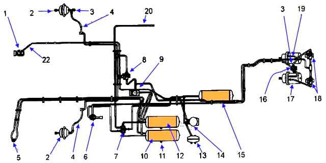
The service brake system consists of wheel brake mechanisms and a pneumatic drive. The diagram of the pneumatic drive of the brake system is shown in Fig. 1.
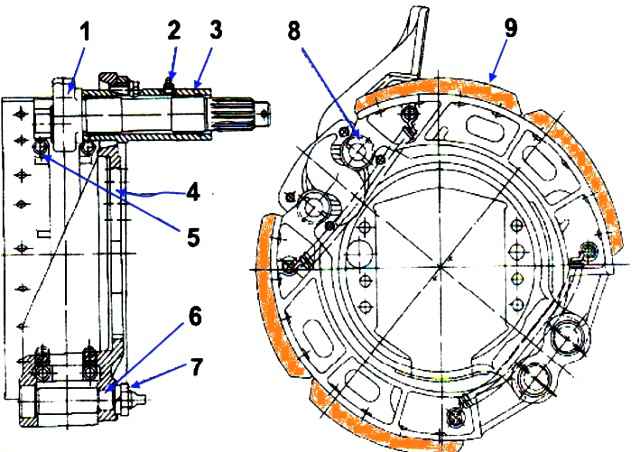
The brake mechanisms of the front and rear wheels (Fig. 2.) are drum type with two brake pads and a brake regulator
The RT-40 brake regulator (Fig. 3.) is designed to transmit force from the pneumatic chamber rod to the shaft expansion cam and to automatically adjust the gap between the linings and the brake drum
Brake maintenance
Replacing brake pads:
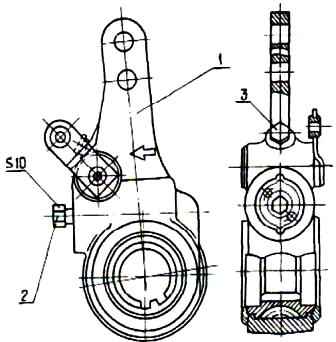
- 1. Press in lock 2 (Fig. 3.) of the brake adjuster and turn it counterclockwise with the key until the brake release knuckle returns to its original position. In this case, the gap between the brake lining and the drum will become maximum.
- 2. Remove the hub together with the drum.
- 3. Remove the tension springs of the pads 5 (Fig. 2.) and brake pads 1
At each removal, the condition of the brake drums should be inspected.
The presence of burrs, cracks and significant wear on the working surface, as well as loosening of the drum attachment to the hub are not allowed.
An increase in the diameter of the brake drums of RZAA axles during operation is allowed by no more than 6 mm.
The maximum diameter of the working surface of the brake drum is 426 mm for RZAA axles and 383 mm for KAAZ axles.
When assembling, lubricate the pad axles with a thin layer of Litol-24 lubricant.
Adjusting wheel brakes
1. To make adjustments easier, remove the brake flaps.

- 2. Loosen nuts 3 securing the eccentric axles of the pads (Fig. 4.).
- 3. Bring the eccentrics closer by turning the axes with marks 4 towards each other (Fig. 5).

- 4. Loosen the nuts and bolts securing the brackets (5 - front, 6 - rear) of the brake chambers (Fig. 4).
- 5. Loosen the mounting bolts of the expansion knuckle support 7 at the rear brake mechanisms (Fig. 5).
- 6. Apply compressed air to the brake chamber at a pressure of 0.1-0.15 mPa (1-1.5 kgf/cm 2), pressing the brake pedal when there is air in the system.
- 7. If there is no compressed air, remove the brake chamber rod pin and, pressing the adjustment lever in the direction of the brake chamber rod stroke when braking, press the pads against the brake drum.
- 8. Center the pads relative to the drum, turning the eccentrics so as to ensure that the pads are in contact with the drum, which can be checked with a feeler gauge through the windows in the front brake flaps or with the rear brake flaps removed.
At a distance of 20 ÷ 30 mm from the outer ends of the linings, a 0.1 mm thick probe should not pass along the entire width of the lining.

- 9. Without stopping the supply of compressed air to the brake chamber, and in the absence of air, without releasing the adjustment lever and holding the axles of the pads from turning, securely tighten the axle nuts (Fig. 6), the bolts securing the brake chamber brackets and the expansion knuckle supports.
- 10. Stop the compressed air supply or release the adjusting lever and attach the brake chamber rod to the lever.
Install rear brake guards.
Preliminary adjustment (installation) of the brake regulator is carried out to obtain the required strokes of the rods after replacing the pads.
1. Release the brakes on the energy accumulators.

- 2. Install the regulator on the brake drive shaft and secure it to the shaft (Fig. 7). The direction of action of the brake chamber force must coincide with the direction of the arrow marked on the regulator body.
- 3. Push the lock into the regulator as far as it will go, pressing its end with your finger.
Holding the lock in the recessed position, rotate it with a key (S=10) clockwise until the holes in the regulator body and the brake chamber fork align (Fig. 7).
- 4. Connect the regulator body to the brake chamber fork and install the regulator drive rod.
- 5. Rotate the lock to the right until it stops, i.e. until the brake pads touch the drum, proceeding as described above.
Then, in the same way, turn the lock to the left by 120-180°. In this case, a gap close to the required one will be established between the brake pads and the drum.
- 6. Release the latch. If it remains recessed, turn it left and right within 30° until it returns to its original position under the action of the spring (Fig. 7).
During operation, the specified stroke value of the brake chamber rod will be maintained by the brake regulator automatically.
The remaining thickness of the brake linings is checked during TO-2 through inspection windows in the brake drums or in the brake shields.
The pads should be replaced when the thickness is less than 4.5 mm. and in the presence of cracks and chips on the working surface.
In case of increased heating of the brake drums or low braking efficiency, it is necessary to check the operation of the adjusting lever of the brake mechanism by measuring the stroke of the brake chamber rod when compressed air is supplied to it from the brake valve at an operating pressure of 0.7-0.8 mPa (Fig. 8 .).
The stroke of the brake chamber rod should be within 29 ± 2 mm.
The rod stroke is not adjusted during operation.
If the rod stroke does not correspond to the above value, it is necessary to check the correct installation of the lever or find out the cause of the violation performance and eliminate it.
If the brake pads were replaced by removing the wheel hub, then after installing the hub you need to carefully pull out the ABS wheel sensor until it comes into contact with the hub ring gear, and then turn the hub two or three turns to obtain the required clearance.
When servicing the brake regulator, you should lubricate it once every two years by pumping 40-50 g of lubricant ZhT-72 TU 38 101345-77 through the hole closed with plug 3 (Fig. 3.)
Attention! Using Litol-24 lubricant to service the regulator leads to its malfunction.
Lubrication of the expansion cam shaft supports is carried out until fresh grease appears from the gaps between the shaft and the bracket.
Attention! To prevent the brake pads of the rear wheels from freezing to the drums after a long stay during sudden temperature fluctuations, it is not recommended to leave the bus with the parking brake on without drying the brakes by smooth braking while driving.
Brake chambers
The front brake chamber is designed to activate the wheel brake mechanisms.
The brake chamber with a spring energy accumulator is designed to actuate the brake mechanisms of the rear axle wheels when the service or parking brake systems are engaged.
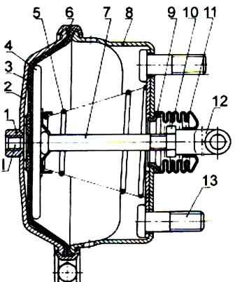
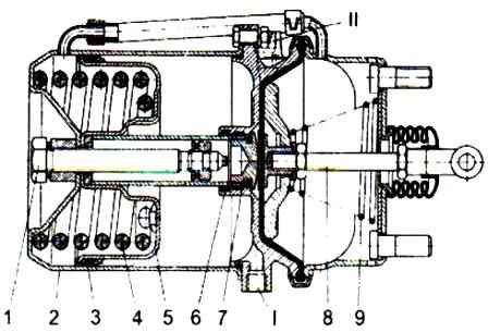
The brake chamber structure is shown in Fig. 9 and fig. 8.
If the seal is broken and the pressure in the parking brake system circuit decreases, air from the cavity under piston 5 through terminal I will escape into the atmosphere through the damaged part of the pneumatic drive, spring 4 will be released and the bus will automatically brake.
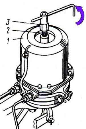
To mechanically release the rear wheels, use key 3 (Fig. 10.) to unscrew screw 2 from the spring energy accumulator to a length of 70 mm.
Attention! Before releasing the brakes, you should protect the bus from rolling away.
Attention! Do not disassemble power accumulators yourself.
The spring energy accumulator contains a powerful spring in a compressed state. It can only be disassembled in a workshop using special tools.
Attention! Before starting to operate the bus, bring the energy accumulators of the brake chambers into working condition, to do this:
- - fill the brake system with air;
- - set the brake valve handle of the parking brake system to the release position and screw in screw 2 until it stops.

")
")
")
")
")